24 / 33
Fail Safe
The Fail Safe function determines receiver response in the event that
transmitter communication is interrupted during flight.
Note
The standard setting, until a change occurs, is the central position.
In case of interference:
♦
Maintain the current
HOLD
position.
♦
All servos programmed to
HOLD
remain at their current position
until a new signal is established with the receiver.
♦
After the fail safe delay, move to the POS
position.
Notes
In case of communication interruption, use the “Cut off in standard mode”
safety option.
To avoid copter motors accidentally starting during testing, pay careful
attention to setting descriptions.
All fail safe settings are automatically saved in the receiver. Fail safe settings
should be restored after changing a receiver and should be deleted in the
previous receiver
Fail-Safe Variant Selection
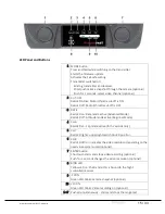
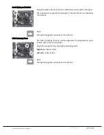
While switching on the transmitter, press and hold the MODE button on
the left of the LED panel. Release the button after having switched the
transmitter on and power the receiver previously bound to the transmitter.
The transmitter BIND LED should then light on yellow.
The transmitter is in “Fail Safe” mode. The different Fail Safe modes (
HOLD
,
ON
/
OFF
and
STANDARD
) can be reached by briefly pressing the
MODE
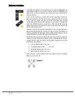
button on the left of the LED panel. Press to cycle between the following
four options:
Active Mode
Status LED and buzzer
Fail Safe
repeated 1x blink and 1x beep
Hold
repeated 2x blinks and 2x beeps
Off
repeated 3x blinks and 3x beeps
Standard
repeated 4x blinks and 4x beeps
FAIL SAFE Mode
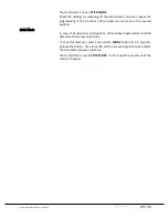
The transmitter beeps once after the first power-on melody. The
transmitter status LED blinks red.
In case of interference, the servos take a pre-set position for a HOLD period
of 0.75 seconds. To align the copter functions, simultaneously bring the
transmitter and receiver controls to their desired positions. Press and hold
the
MODE
button for 3-4 seconds until the positions are stored as fail safe.
Positions will automatically be saved for future reference. After releasing
the button, the status LED and the acoustic signal should indicate the
transmitter power-on status.
Содержание mz-10c
Страница 1: ...MANUAL mz 10c HoTT2 4GHztransmitterforcoptersanddrones No S1001 G1andS1001 G1 77 mz 10 ...
Страница 28: ...28 33 ...
Страница 33: ...S1001 G1 and S1001 G1 77 USA V1 0 33 33 Notes ...


