Code 17 Code 66
Throttle Reduction Automatic Program
Switchable, Single-Sided Throttle Throw Reduction Automatic Flight Manoeuvre for Type 1 – 5 Models
28
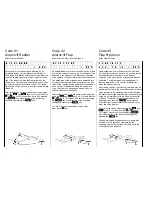
R E D U C E D T H R O T T L E
F U L L V A L U E 1 0 0 %
Code 17 permits programming a reduction of the
carburettor control range, switchable by an external
switch allocated by code 23. The effects corresponds
to a dual rate function for channel 1, the neutral point
of which is not located at the stick neutral, but at one
of the end points. This options permits the avoidance
of exceeding a critical carburettor opening when the
throttle stick is in the full throttle position or falling
below a set carburettor opening, although the stick is
on the lower stop.
After calling code 17, the lower line of the display will
either show the word OFF, indicating that the switch
allocated by code 23 is in the OFF position, or if the
switch is in the ON position, it will show the adjusted
value. The stylised stick right of “FULL” indicates that
position of the throttle stick, where throttle reduction is
to become effective. It can be reversed by pressing
the
TURN
key. Servo throw can be adjusted in that
direction via the
INC
and
DEC
keys, in % of normal
throw. The end position of the throttle servo at the
opposite end remains unchanged.
P R O G R A M - A U T O M .
P R O G R A M 3 O F F
Prior to programming a switch has to be allocated by
code 23. After its activation, channel 1 – 4 data for
four different aerobatic manoeuvres (frequently Barrel
Rolls, Snap Rolls) can be programmed and called via
button while the letter is pressed down and hold.
Programmed mix functions, if any, having their inlets
at one of channels 1 – 4 will react as if the stick
concerned had been moved to the programmed
position. Channel trim remains effective in the normal
manner, even when activated programmed position.
Selection of stored manoeuvres is performed via two
switches wired to connections A and B as follows:
Switch A
Switch B
Manoeuvre
ON
ON
0
OFF
ON
1
ON
OFF
2
OFF
OFF
3
Activation of a selected manoeuvre is performed by
an intermediate switch (order No. 4160/11) wired to
connection C, or via a momentary button.
As a precaution against accidental activation of a
manoeuvre, a switch can be allocated by code 23,
preferably a locking safety switch (order No. 4147/1).
This safeguarding measure can be dispensed with
though if this function remains permanently activated
by the setting in code 23.
On calling code 66, “INH” will appear on the lower line
of the display if no switch has been allocated by code
23, or the allocated switch has not been turned on.
If the button at position C has not been pressed, the
display will read:
P R O G R A M - A U T O M .
P R O G R A M N O F F
Symbol ‘n’ indicates manoeuvre 0 – 3, which has
been selected by switches A + B.
If button C is pressed, the display will read
1 : + 0 % 2 : + 0 %
3 : + 0 % 4 : + 0 %
In each case the arrow indicates that control function
the setting of which can be changed. The selection is
performed with keys
1
…
4
. Keys
INC
and
DEC
permit adjustment of the magnitude of control surface
deflection, while key
7
reverses the direction of
deflection. Using key
8
the selected control can be
set to follow the relevant control stick, while the other
servos occupy their programmed positions. In this
case the display will read “VAR” instead of a
percentage value.
Содержание mc-18
Страница 1: ...1...
Страница 10: ...Block Diagram NORMAL 10...
Страница 11: ...Block Diagram NORMAL DIFF 11...
Страница 12: ...Block Diagram DELTA DIFF 12...
Страница 13: ...Block Diagram UNIFLY DIFF 13...
Страница 14: ...Block Diagram Quadro Flap 14...
Страница 15: ...Block Diagram F3B 3 wing servos 15...
Страница 16: ...Block Diagram F3B 4 wing servos 16...


