Code 34 Code 13 Code 14
DR/EX Switch DUAL RATE EXPONENTIAL
Dual Rate / Exponential Switch Allocation Adjustable Servo Throw Reduction Progressive Control Characteristics
24
D R 2 3 4 E X 2 3 4
S W I 9 9 9 9 9 9
The switches for the dual-rate and exponential
functions are allocated using code 34. In doing so it is
possible to trigger several control functions
simultaneously without using multi-function switches.
Due to the possibility of reversing switch functions via
the
DEC
key, dual-rate and exponential can be
coupled with ant other function switch.
Allocation and reversing of external switches
After calling the designations of the control functions
will appear in the upper line of the display for dual-
rate and exponential, with the allocated switches
concerned in the lower line. The small arrow in the
upper line indicates whether the allocation for dual-
rate or exponential is being performed, and it’s
position can be changed using the
INC
and
DEC
keys.
Allocation of the switches is performed by pressing
the key for the input function (
2
…
4
) followed by the
switch number, if necessary pressing
DEC
first to
reverse the switch polarity.
After all allocations have been made, press
ENTER
to store the settings.
Using code 73, switch position, the number and
orientation of the switches can be found quickly and
reliably.
D U A L R A T E
p u s h c h k e y 2 - 4
The dual-rate function permits in-flight switching of
control characteristics, with the range of adjustment
being variable between 0 – 125% of the normal range
for each of the two switch positions. The switched
must have been allocated beforehand using code 34.
Dual rate refers directly to the corresponding stick
function, independent of whether it affects a single
servo or, optionally via complex mixing and coupling
functions, several ones.
After calling code 13 the desired control functions can
be selected via keys
2
…
4
:
2
= Ailerons
3
= Elevator
4
= Rudder
Adjustments of the control curve are performed using
the
INC
and
DEC
keys after the switch has been
moved to the appropriate position (P0/P1).
E X P O N E N T I A L
p u s h c h k e y 2 - 4
Exponential control permits obtaining sensitive control
of a model near the neutral position of the function
concerned, whilst maximum travel remains
unaffected. The degree of progression can be
adjusted from 0 to 100%, with 0 corresponding to
normal linear travel.
The three control functions ailerons, elevator and
rudder can be switched from linear to progressive
control using switches, which have been allocated by
code 34 beforehand, or from one progressive
adjustment to another progressive one.
These adjustments refer directly to the corresponding
stick function, no matter whether it affects a single
servo or, optionally via complex mixing and coupling
functions, several ones.
After calling code 14 the desired control functions can
be selected via keys
2
…
4
:
2
= Ailerons
3
= Elevator
4
= Rudder
Adjustments of the control curve are performed using
the
INC
and
DEC
keys after the switch has been
moved to the appropriate position. (P0/P1)
In some cases linking the two functions of dual-rate
and exponential may make sense. This is achieved
by using the same switch when allocating the dual-
rate and exponential switches using code 34.
Содержание mc-18
Страница 1: ...1...
Страница 10: ...Block Diagram NORMAL 10...
Страница 11: ...Block Diagram NORMAL DIFF 11...
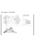
Страница 12: ...Block Diagram DELTA DIFF 12...
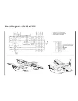
Страница 13: ...Block Diagram UNIFLY DIFF 13...
Страница 14: ...Block Diagram Quadro Flap 14...
Страница 15: ...Block Diagram F3B 3 wing servos 15...
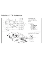
Страница 16: ...Block Diagram F3B 4 wing servos 16...


