Code 37 Code 43 Code 11
Signal Generator Allocation V-Tail Servo Reverse
Allocation of Operating Elements Channels 5 – 9 V-Tail Mixer Reversing Direction of Servo Rotation
21
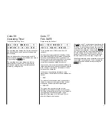
P O R T 5 6 7 8 9
I N P U T 5 6 7 8 9
In some cases, for individual models, it may be
desirable to have certain operating elements, such as
slider-type potentiometers or channel switches affect
other function outputs than those to which they have
been allocated by the internal connection.
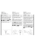
Code 37 permits free choice of allocation of the
operating elements to the function outlets without
changing the internal connections. In addition it is
possible to have one operating element affect several
function outputs.
After selecting, the function inputs (operating
elements) appear in the upper line of the display
identified by the socket 5…9, and the output to which
they have been allocated appears in the lower line.
Signal generator 7 is, for example, the slider-type
potentiometer is connected to plug station 7.
To allocate one of the function inputs to another
operating element, select the function concerned by
one of the keys …
9
, whereupon a question mark
symbol appears in the lower line below the selected
function. Pressing key
5
…
9
allocates this function
to the desired operating element, which may have
also been allocated to another function, affecting both
functions in that case.
Normal allocation will be restored by pressing the
CLEAR
key.
In the case that a signal generator action should be
undesirable, in special case such as a dummy mixer,
the signal generator concerned can be turned off via
code 72.
m c - 1 8 E M O D E L 1
V - T A I L O F F
With models fitted with a V-tail the functions of
elevator and rudder are mixed in a such a manner
that in the case of the elevator both control surfaces
are moved up and down (in the same direction), but in
opposite directions (one up, one down) the case of
rudder. Unlike mechanical solutions where the
elevator servo and the rudder servo actuate both
surfaces via a suitable mechanical mixer, each
control surface is operated by a separate servo. This
solution provides the advantage that control of the V-
tail is slop-free and accurate, and that in addition,
higher control forces are available.
The V-tail mixer can be used for all types of models,
naturally with the exception of helicopters (types 8
and 9) and Deltas and flying wing models (type 3) as
in these case elevator function and aileron function
are mixed anyway.
After calling code 43, the V-tail mixer can be turned
on via the
INC
and
DEC
keys, and turned off by
pressing
CLEAR
.
The elevator/rudder mix ration can be modified via the
dual-rate adjustment, code 13.
R E V . S W 2 3 5 8
N O R M 1 4 6 7 9
Code 11 permits changing the direction of rotation of
servo to those required in a model, so the linkages
etc., can be installed without paying attention to the
initial direction of rotation of the servos in question.
After calling code 11, the direction of rotation of all
servos will be simultaneously indicated on the display
by their numbers 1…9 with the numbers appearing in
the bottom line indicating normal rotation, and those
appearing in the upper line indicating reversed
rotation.
Important:
The numerals of the servo designation always refer to
the receiver outlet to which the servo is connected.
Any conformity with the numbering of the control
function inputs of the transmitter would be purely
coincidental. They won’t occur normally because of
the complex special programs of these hi-tech
models. For that reason a change of allocation of
control functions (code 57) won’t affect the numbering
and direction of rotation of the servos.
Содержание mc-18
Страница 1: ...1...
Страница 10: ...Block Diagram NORMAL 10...
Страница 11: ...Block Diagram NORMAL DIFF 11...
Страница 12: ...Block Diagram DELTA DIFF 12...
Страница 13: ...Block Diagram UNIFLY DIFF 13...
Страница 14: ...Block Diagram Quadro Flap 14...
Страница 15: ...Block Diagram F3B 3 wing servos 15...
Страница 16: ...Block Diagram F3B 4 wing servos 16...


