background image

Code 51, 33, 61 and 71 
Free Program Mixer 

Programming Mixers and Dummy Mixers


30 

In addition to the available mix and coupling 
functions, all model programs provide a number of 
freely programmable mixers. In the case of type 1 - 3 
models nine mixers are at the disposal of the user, 
types 4 and 5 have four mixers available, for F3B 
types 6 and 7 a total of seven, and for the helicopter 
types 8 and 9 there are four mixers available. 

The mixers link an input signal to an outlet signal, with 
allocation performed by code 51. As any optional 
control function can be fed as an inlet signal, the 
outlet signal affects any desired control channel, not a 
control function. Distinguishing between these two 
terms is of utmost importance. Control function refers 
to the outlet signal of an operating element, that is a 
stick with or without trim, slider, rotary control or a 
channel switch, which in the course of the ensuing 
action passes through all the mix and coupling 
functions of the model program. A control channel is 
the outlet signal for a specific receiver connection, 
which until it arrives at the servo can only be affected 
by throw adjust, neutral point adjust, throw reduction 
or control surface reversing. 

Mixers may also be switched in series for special 
applications, which is say that in addition to the 
control function proper all other preceding mixers can 
also be used as inlet functions. All F3B mixers (see 
F3B programs) and all freely programmable mixers 
with a lower number are considered as preceding 
mixers. 

To give you an idea, imagine that instead of a control 
function (see above) the outlet signal of a control 
channel is used as the input function of the mixer 
before it passes through throw adjust, neutral point 
adjust, throw reduction or servo reversing. 

Each of the freely programmable mixers can be 
turned on and off by one of the switches allocated 
using code 33. 

Vital parameters of the mixers are the mix quotas 
which determine how strongly the inlet signal affects 
the control channel wired to the outlet of the mixer. 
They also set the direction of the mixed signal and the 
neutral point of the mixer, that is the point on the 
control characteristic curve of the inlet signal where 
the mixer does not affect the control channel wired to 
the outlet (normally this will be the neutral point of the 
control stick). 

In the case of freely programmable mixers, these 
parameters can be adjusted over a wide range. The 
neutral point can be shifted to any desired point of the 
control throw of the operating element wired to the 
inlet (the distance from neutral point is called the 
OFFSET). The mixing ratios can also be adjusted in 
both directions above and below the neutral point, 
either in symmetrical (code 61) or asymmetrical 
(code 71) fashion. The mix direction can also be set 
for both sides using codes 61 and 71 by setting the 
values as + or -. 

As a single control function can serve as inlet for an 
optional number of mixers, and any number of mixers 
may affect a control channel, the freely programmable 
mixers permit achievement of special, highly complex, 
applications. 

DUMMY Mixer: 
A so called dummy function may also be allocated as 
an inlet signal, that is a control function that is not 
available as a true operating element, but provides a 
consistent control signal. In this manner it is possible 
to make use of a control channel as an operating 
element by allocating a dummy mixer and having the 
outlet of the mixer affect the channel concerned. 
Throw of the switch is then adjusted by the mix quota 
and mix direction of the dummy mixer. A dummy 
mixer also permits mixing an additional constant trim 
signal dependent on a switch allocated by code 33. 

Practical Example of a Dummy Mixer 

An external switch is wired to socket 1, switches a 
servo connected to receiver output 8,for example 
operating a glider tug release device. 

Programming Sequence: 

1. Reset mixer from 0 to 8 via code 51. Inlet function 

0 is obtained by pressing the 

 INC 

 key. 

2. Input mix quota and direction via codes 61 and 

71. 

3. Allocate external switch to socket 1 via code 33. 


Содержание mc-18

Страница 1: ...1...

Страница 2: ...flexibility of adaptability to individual requirements or demands of the operator necessitate the provision of specific allocations before calling and setting up the options depending on them Thus th...

Страница 3: ...icopter Type 8 60 87 Description of Options Helicopter Type 9 87 Helicopter Programming Examples I Basic Settings 1 Preparations 88 2 Executing a Reset 88 89 3 Selection of Model Memory 89 4 Input Nam...

Страница 4: ...39 53 FLAP TRIM ASS Flap Trim Assignment 39 54 DIFF REDUCT Reduction of Aileron Differential 43 56 56 56 56 MODEL SELECT Select Model 18 60 Model Type Display Reads Meaning Described on Code Fixed Win...

Страница 5: ...en programming a new model This step determines which of the options will be available in the course of the programming process 1 TX of series 89 and later are designed for 30 model memories Basic Pro...

Страница 6: ...rface being controlled by an independent servo and with the correct mixture of aileron and elevator control provided for already All other options are available with restrictions including the nine fr...

Страница 7: ...ssing key LIST DM then pressing INC to go forwards and DEC to go backwards Aster the desired code number has been found the program in question can be selected using the ENTER key The value can then b...

Страница 8: ...order no 4160 22 is connected for example to switch aileron differential code 22 the two plugs must be plugged into horizontally adjacent stations only e g 4 and 8 never one above the other e g 3 and...

Страница 9: ...or Switches 9 The switch allocation is freely programmable that is any switch can be programmed for any desired function These practical examples of switch allocations are meant to simplify programmin...

Страница 10: ...Block Diagram NORMAL 10...

Страница 11: ...Block Diagram NORMAL DIFF 11...

Страница 12: ...Block Diagram DELTA DIFF 12...

Страница 13: ...Block Diagram UNIFLY DIFF 13...

Страница 14: ...Block Diagram Quadro Flap 14...

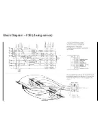
Страница 15: ...Block Diagram F3B 3 wing servos 15...

Страница 16: ...Block Diagram F3B 4 wing servos 16...

Страница 17: ...ow Adjustments 22 19 THROW LIMIT Servo Throw Reduct ion 22 79 SERVO SLOW D Servo Slow Set up 23 Further Adjustments 16 TRACE RATE Adjust Effect of Operating Stick 23 31 THR BRK MIDP Set Channel 1 Mid...

Страница 18: ...tivated by ENTER If the CLEAR key is pressed instead of ENTER complete deletion of the selected model data can be initiated This process is be performed by the ENTER key and aborted by any other key I...

Страница 19: ...model programs which can be stored in the transmitter at the same time it will not be easy to remember the number of a model the data of which have been stored in memory For this reason the name of a...

Страница 20: ...an be shown at the same time on the display the latter can be moved window style over the two lines showing the allocations When the arrow points to the outermost right function the next function will...

Страница 21: ...ch a manner that in the case of the elevator both control surfaces are moved up and down in the same direction but in opposite directions one up one down the case of rudder Unlike mechanical solutions...

Страница 22: ...selected servo will be indicated with a prefix or indicating the side For adjustment and display the operating element control stick slider rotary control or switch has to be moved to the end station...

Страница 23: ...Control travel resulting from actuating an operating element on function inputs 6 8 is adjusted by code 16 The range of adjustments amounts to 0 150 of the normal range Unlike code 12 servo travel ad...

Страница 24: ...range for each of the two switch positions The switched must have been allocated beforehand using code 34 Dual rate refers directly to the corresponding stick function independent of whether it affec...

Страница 25: ...of the trim levers as a deviation from the neutral position With the aid of the display the trim levers are then shifted to the neutral position a step which does not change the trim positions of the...

Страница 26: ...copied has been entered this name will also be transferred to the copy but with a symbol added to the last letter of the name to distinguish it from the original For safety s sake model memories that...

Страница 27: ...ons is operated by a separate servo permitting the ailerons servo to be installed in the wing ensuring slop free and reproducible adjustments even with 2 piece wings The ratio of differential can be a...

Страница 28: ...letter is pressed down and hold Programmed mix functions if any having their inlets at one of channels 1 4 will react as if the stick concerned had been moved to the programmed position Channel trim r...

Страница 29: ...by turning on the correspondingly programmed misers flaps can be lowered when throttling the engine and the elevator re trimmed Auto Landing or dual rates may be switched to increase control surface...

Страница 30: ...s which determine how strongly the inlet signal affects the control channel wired to the outlet of the mixer They also set the direction of the mixed signal and the neutral point of the mixer that is...

Страница 31: ...lower line and then entering the desired switch number the polarity of which can be reversed by pressing the DEC key first The phantom switch 9 can be used in which case the mixer remains permanently...

Страница 32: ...its operation via the keyboard Stopwatch with normal display The stopwatch with normal display may be programmed by allocating a switch to function CLK using code 23 A prerequisite is that the alarm...

Страница 33: ...tored in the receiver In this manner interference of short duration will be eliminated In the case of longer lasting disturbance of the transmissions the operator may choose between two options 1 HOLD...

Страница 34: ...els is not possible Activation of the keyboard lock is performed using code 88 and entering an optional 3 figure combination using keys 1 9 followed by the ENTER key The lock becomes effective by turn...

Страница 35: ...an endless loop until interrupted by pressing the ENTER key In this way the receiver can be checked over a longer period S E R V O P O S p u s h c h k e y 1 10 The actual position of each servo can be...

Страница 36: ...hese requirements the models of this contest normally feature plain flaps so they can be adapted to the flight tasks of duration distance and speed as well as the launch phase In addition they also se...

Страница 37: ...with optional storing of adjustment data etc simplify handling of a model for the demanding contest flyer and assist him in his endeavour to achieve optimum performance The two F3B programs differ on...

Страница 38: ...e INC and DEC key respectively As not all of the available functions can be shown at the same time on the display the latter can be moved window style over the two lines showing the allocations When t...

Страница 39: ...nal generator of channel 6 or 7 or by neither of these For example you may actuate the flaps for the duration phase by slider type control 6 for distance flight by a switch module providing three swit...

Страница 40: ...by an external switch set with code 23 After calling code 42 the mix quota can be adjusted using the INC and DEC keys in 1 steps and the 6 or 8 key in 10 steps and set to 0 by pressing the CLEAR key w...

Страница 41: ...tion with their neutral positions corresponding to the programmed settings On deactivation of the trimmers the adjusted value will be stored It if thus possible to establish optimum settings in flight...

Страница 42: ...ht with flaps at neutral position To this end the operating element concerned is set accordingly and then the STORE key is pressed The offset from the neutral position is shown on the lower line of th...

Страница 43: ...quota having been set to 0 they are effectively inactive Code 44 Spoilers Elevator Code 45 Spoilers Flaps Code 46 Spoilers Ailerons To activate them input the corresponding code number whereupon the a...

Страница 44: ...You have installed the module into the transmitter as per the instructions Close the case of the transmitter again and turned the transmitter on The display will read m c 1 8 E M O D E L 1 9 6 V P C...

Страница 45: ...s Using the TURN key changes between uppercase and lowercase letters If you have entered an incorrect letter you can backspace using the CLEAR key and the correct it Having entered the complete name i...

Страница 46: ...e accordingly Terminate the input by pressing the ENTER key and you are once again back in command mode T A X I C U P 1 F U N C T I O N 5 7 ENTER T A X I C U P 1 M O D E 1 2 T A X I C U P 1 M O D E 2...

Страница 47: ...stick to increase engine power To this end input 1 8 ENTER The display then reads IDLE R TRIM OFF Using the INC and DEC keys you may now switch to and fro between and means pushing for full throttle...

Страница 48: ...e remaining models by 9 4 ENTER 1 ENTER 3 ENTER ENTER 9 4 ENTER 1 ENTER 4 ENTER ENTER 9 4 ENTER 1 ENTER 7 ENTER ENTER 9 4 ENTER 1 ENTER 3 0 ENTER ENTER T A X I C U P 1 F U N C T I O N 9 4 ENTER C O P...

Страница 49: ...nsmitter and receiver on now and check the function of the control surfaces Most likely one or other of the servos will be found to rotate in the wrong direction it would be matter of sheer luck if no...

Страница 50: ...t case a lot of obtainable control precision will be lost This of course is not limited to the control surfaces but also applies to the throttle as well Here again the linkage should be attached to th...

Страница 51: ...are deluxe options with the aid of which problems encountered when flying certain models can be solved Flying certain manoeuvres can be made easier and or advantages can be gained over other contestan...

Страница 52: ...plain flaps and flaperons of large sailplane models Here the threshold action can be set just short of a point where otherwise linkages or hinges would flex or deform T A X I C U P 1 F U N C T I O N...

Страница 53: ...im adjustment even after a change of models To store the in flight established trim data input 5 9 ENTER STORE The display now indicates in it s lower line the trim lever offset you had set from the n...

Страница 54: ...ENTER key Important Always trigger the copy process by the ENTER key on the receiving unit first m c 1 8 E M O D E L 6 F U N C T I O N 9 4 ENTER C O P Y F R O M M O D E L K E Y 1 7 O R DEC C O P Y F R...

Страница 55: ...nit ready to transmit copy Trigger copying process with the ENTER key Important Always trigger the copy process by the ENTER key on the receiving unit first m c 1 8 E M O D E L 6 F U N C T I O N 9 4 E...

Страница 56: ...keys 1 9 or INC and DEC Call the model memory to be copied into using the keys 1 9 or INC and DEC such as memory 3 Terminate the copy program selection using the ENTER key Transmitter ready to copy Tr...

Отзывы: