


Zodiak Installation and Service Manual
31
Functional Overview
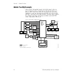
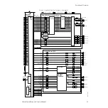
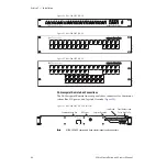
Figure 8. Simplified Video Flow Diagram — Bottom Hal
Control Processor DSK
Input/Xpt/
Sync Gen
Deserializer and Reclock
Serializer
Delay
Video or Key Signals
Program A
Program A
Aux 1
Aux 1
Aux 2
Aux 2
Aux 3
Aux 3
Aux 4
Aux 4
Aux 5
Aux 5
Switched PVW
Stillstore 1
Key 1 Video
Key 1 Key
Key 2 Video
Key 2 Key
Key 3 Video
Key 3 Key
A Video
B Video
Stillstore 1
Stillstore 2
Stillstore 3
Stillstore 4
Stillstore 2
Switched
Preview
Still Store
Preview A
Preview B
Program B
Program B
Stillstore 1
Background
Generator
Sync
Generator
Stillstore 2
Stillstore 3
Stillstore 4
Program A
Program B
PGM/PST
DSK Mixer
Bkg 1
Bkg 2
Single Mix Effect (3-M/E Switchers only)
M/E 3 Outputs
M/E 3 Inputs
Key 1 Video
Key 1 Key
Key 2 Video
Key 2 Key
Key 3 Video
Key 3 Key
Key 4 Video
Key 4 Key
A Video
B Video
Utility Video
Key 1 Video
Key 1 Key
Key 2 Video
Key 2 Key
Key 3 Video
Key 3 Key
Key 4 Video
Key 4 Key
Key 1 Video
Key 1 Key
Key 2 Video
Key 2 Key
Key 3 Video
Key 3 Key
Key 4 Video
Key 4 Key
A Video
B Video
Utility Video
Video
Processor
Transform
Engines
Mixer
Key Wipe Gen
4 Simple
Complex
Wipe Gen
Program
Program
Preview
Preview
Aux/Send 10
Aux/Send 11
Aux Send 12
Aux/Send 13
M/E 3 PGM
Aux/Return 10
Aux/Return 11
Aux/Return 12
Aux/Return 13
M/E 3 PVW
Analog 525/625
Reference Input
Xpts
1 – 64
8126_00_03r0


