FC8600-UM-251-9370 7-21
7 ADJUSTMENT
(7)
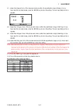
Adjust the 40g-pen force. If the measured value is within the specification range (40±4g) or if you
have input the recorded value, press the ENTER key to store the setting. The next specified pen force
appears.
(8)
Adjust the 120g-pen force. If the measured value is within the specification range (120±10g) or if you
have input the recorded value, press the ENTER key to store the setting. The next specified pen force
appears.
(9)
Adjust the 300g-pen force. If the measured value is within the specification range (300±20g) or if you
have input the recorded value, press the ENTER key to store the setting. The next specified pen force
appears.
(10)
Adjust the 400 g-pen force. If the measured value is within the specification range or if you have input
the recorded value, press the ENTER key to store the setting.
Note: When adjusting the pen force, it is important to do it quickly. Delaying the pen force adjustment
changes the temperature of the actuator and causes artificially lower readings. When this happens the
actual pen force may be higher than the specification. This is especially true for the upper pen force
adjustment.
(11) Press the NEXT key to complete this adjustment.
(12) Turn off the power to exit from the adjustment menu.
Specification of the actual pen force
Specified pen force
Actual force range
FC8600
10g
8 to 12g
40g
36 to 44g
120g
110 to 130g
300g
280 to 320g
400g
380 to 420g
Содержание FC8600-100
Страница 1: ...CUTTING PLOTTER SERVICE MANUAL FC8600 60 75 100 130 160 FC8600 UM 251 07 9370 ...
Страница 2: ......
Страница 4: ...FC8600 UM 251 9370 II ...
Страница 32: ......
Страница 103: ...FC8600 UM 251 9370 7 43 7 ADJUSTMENT ...
Страница 118: ...FC8600 UM 251 9370 8 15 8 TROUBLESHOOTING 11 When testing is completed turn off the power to the plotter ...
Страница 124: ...FC8600 UM 251 9370 9 2 9 PARTS LIST Outer Casing 4 6 2 3 9 13 11 12 14 15 10 1 16 8 7 5 ...
Страница 131: ...FC8600 UM 251 9370 9 9 9 PARTS LIST Main Frame 1 3 4 5 7 8 9 10 11 12 6 2 15 16 13 14 20 21 22 17 18 19 ...
Страница 141: ...FC8600 UM 251 9370 10 3 10 BLOCK DIAGRAMS AND CIRCUIT DIAGRAMS 10 2 2 Main Board CONNECTOR ...
Страница 142: ...FC8600 UM 251 9370 10 4 10 BLOCK DIAGRAMS AND CIRCUIT DIAGRAMS 10 2 3 Main Board MOTOR DRIVER ...
Страница 143: ...FC8600 UM 251 9370 10 5 10 BLOCK DIAGRAMS AND CIRCUIT DIAGRAMS 10 2 4 Main Board FPGA ...
Страница 144: ...FC8600 UM 251 9370 10 6 10 BLOCK DIAGRAMS AND CIRCUIT DIAGRAMS 10 2 5 Main Board I F ...
Страница 145: ...FC8600 UM 251 9370 10 7 10 BLOCK DIAGRAMS AND CIRCUIT DIAGRAMS 10 2 6 Main Board MEMORY ...
Страница 146: ...FC8600 UM 251 9370 10 8 10 BLOCK DIAGRAMS AND CIRCUIT DIAGRAMS 10 2 7 Main Board Power When the LAN is connected ...
Страница 147: ...FC8600 UM 251 9370 10 9 10 BLOCK DIAGRAMS AND CIRCUIT DIAGRAMS 10 2 8 LAN Board ...
Страница 148: ...FC8600 UM 251 9370 10 10 10 BLOCK DIAGRAMS AND CIRCUIT DIAGRAMS 10 2 9 Light Pointer ...
Страница 149: ...FC8600 UM 251 9370 10 11 10 BLOCK DIAGRAMS AND CIRCUIT DIAGRAMS 10 2 10Pen Relay Board ...
Страница 151: ...FC8600 UM 251 9370 10 13 10 BLOCK DIAGRAMS AND CIRCUIT DIAGRAMS 10 2 13Control Panel Board ...
Страница 152: ...FC8600 UM 251 9370 10 14 10 BLOCK DIAGRAMS AND CIRCUIT DIAGRAMS 10 2 14Cam Sensor Board ...

