FC8600-UM-251-9370 7-2
7 ADJUSTMENT
7.2 Mechanical Adjustments
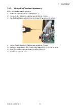
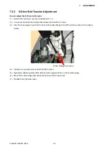
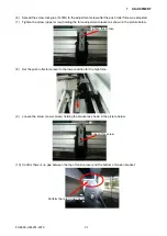
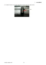
7.2.1 Y-Belt Tension Adjustment
How to adjust the Y-belt tension
Belt tension adjustment is required to set proper tension of the belt to maintain machine performance, reduce
overshoot, and correct any out-of-phase condition in the Y-axis.
(1) Detach the right side cover (see Subsection 6.1.1).
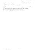
(2) With the Y-slider on the Y-rail and the belt attached, adjust the Y-tension pulley adjustment screws that
hold the Y-tension pulley onto the left side plate in order to tighten the Y-slider belt. Do not over-tighten.
Move the Y-slider from left to right several times to verify that the tension is set correctly.
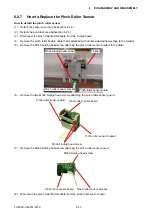
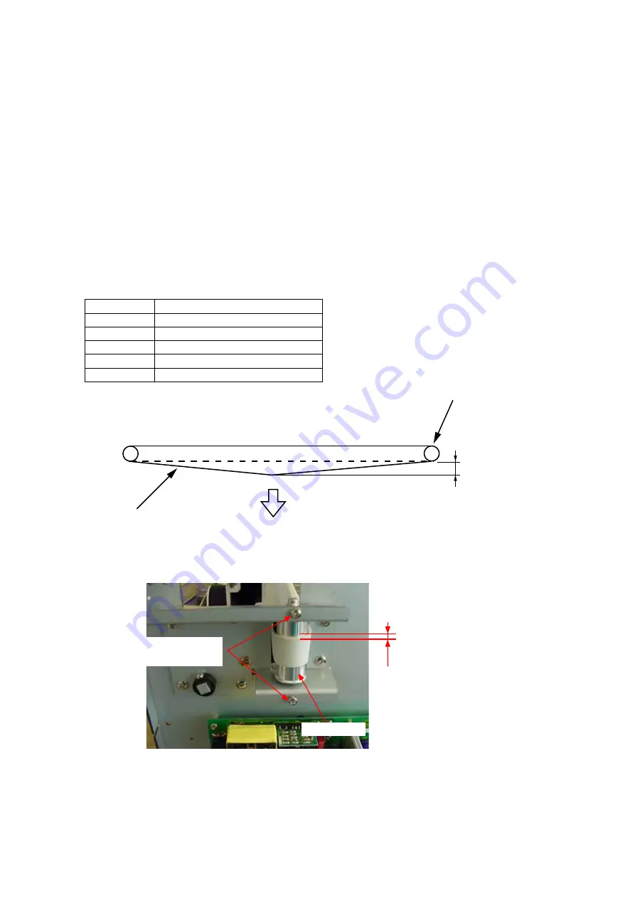
(3) Move the Y-slider all the way to the right and pull the belt 20 mm towards the center using a force
gauge. Adjust the Y-tension pulley adjustment screws evenly until the tension reads as follows:
Specification of the Belt Tension
Model
Force gauge reading specification
FC8600-60
700 g+50
FC8600-75
700 g+50
FC8600-100
700 g+50
FC8600-130
700 g+50
FC8600-160
700 g+50
20 mm
700 g + 50g
Y idler pulley
Y belt
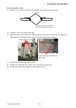
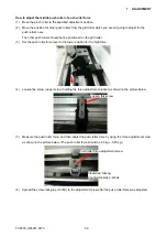
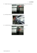
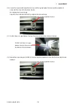
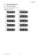
(4) Verify that the Y-slider belt is centered and does not move up and down when the Y-slider is moved from
left to right several times. The Y-slider belt should not move up and down more than 1.5 mm.
The Y-slider belt should
not move up and down
more than 1.5 mm.
Y idler pulley
Y-tension pulley
adjustment screws
(5) If the Y-slider belt continues to move up and down or exhibits less clearance, re-adjust the Y-tension
pulley adjustment screws and check the belt tension again.
(6) Reattach the right side cover.
Содержание FC8600-100
Страница 1: ...CUTTING PLOTTER SERVICE MANUAL FC8600 60 75 100 130 160 FC8600 UM 251 07 9370 ...
Страница 2: ......
Страница 4: ...FC8600 UM 251 9370 II ...
Страница 32: ......
Страница 103: ...FC8600 UM 251 9370 7 43 7 ADJUSTMENT ...
Страница 118: ...FC8600 UM 251 9370 8 15 8 TROUBLESHOOTING 11 When testing is completed turn off the power to the plotter ...
Страница 124: ...FC8600 UM 251 9370 9 2 9 PARTS LIST Outer Casing 4 6 2 3 9 13 11 12 14 15 10 1 16 8 7 5 ...
Страница 131: ...FC8600 UM 251 9370 9 9 9 PARTS LIST Main Frame 1 3 4 5 7 8 9 10 11 12 6 2 15 16 13 14 20 21 22 17 18 19 ...
Страница 141: ...FC8600 UM 251 9370 10 3 10 BLOCK DIAGRAMS AND CIRCUIT DIAGRAMS 10 2 2 Main Board CONNECTOR ...
Страница 142: ...FC8600 UM 251 9370 10 4 10 BLOCK DIAGRAMS AND CIRCUIT DIAGRAMS 10 2 3 Main Board MOTOR DRIVER ...
Страница 143: ...FC8600 UM 251 9370 10 5 10 BLOCK DIAGRAMS AND CIRCUIT DIAGRAMS 10 2 4 Main Board FPGA ...
Страница 144: ...FC8600 UM 251 9370 10 6 10 BLOCK DIAGRAMS AND CIRCUIT DIAGRAMS 10 2 5 Main Board I F ...
Страница 145: ...FC8600 UM 251 9370 10 7 10 BLOCK DIAGRAMS AND CIRCUIT DIAGRAMS 10 2 6 Main Board MEMORY ...
Страница 146: ...FC8600 UM 251 9370 10 8 10 BLOCK DIAGRAMS AND CIRCUIT DIAGRAMS 10 2 7 Main Board Power When the LAN is connected ...
Страница 147: ...FC8600 UM 251 9370 10 9 10 BLOCK DIAGRAMS AND CIRCUIT DIAGRAMS 10 2 8 LAN Board ...
Страница 148: ...FC8600 UM 251 9370 10 10 10 BLOCK DIAGRAMS AND CIRCUIT DIAGRAMS 10 2 9 Light Pointer ...
Страница 149: ...FC8600 UM 251 9370 10 11 10 BLOCK DIAGRAMS AND CIRCUIT DIAGRAMS 10 2 10Pen Relay Board ...
Страница 151: ...FC8600 UM 251 9370 10 13 10 BLOCK DIAGRAMS AND CIRCUIT DIAGRAMS 10 2 13Control Panel Board ...
Страница 152: ...FC8600 UM 251 9370 10 14 10 BLOCK DIAGRAMS AND CIRCUIT DIAGRAMS 10 2 14Cam Sensor Board ...

