FC8600-UM-251-9370 8-2
8 TROUBLESHOOTING
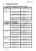
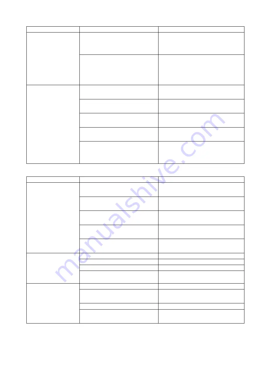
Symptom
Verification item
Solution
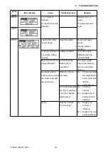
The plotter can’t
recognize the X direction
of the media size.
(1) Is there any dust on the front
media sensor and the rear
media sensor?
Yes ....Clean the front media sensor and
the rear media sensor.
No .....Verify item (2).
(2) Are the front media sensor and
the rear media sensor cables
securely connected to each
connector?
No .....Connect the cables securely.
Yes ....Replace the sensor(s).
The media is fed at an
angle.
(1) Are the pinch rollers worn
down?
Yes ....Replace the pinch roller(s).
No .....Verify item (2).
(2) Is there anything on the drive
roller?
Yes ....Clean the drive roller with a brush.
No .....Verify item (3).
(3) Do the pinch rollers have the
correct pressure?
No .....Replace the pinch roller spring(s).
Yes ....Verify item (4).
(4) Is the drive roller worn down?
Yes ....Replace the drive roller.
No .....Verify item (5).
(5) Is the drive roller attached
correctly?
Yes ....Replace the bearing of the drive
roller.
No .....Attach the drive roller correctly.
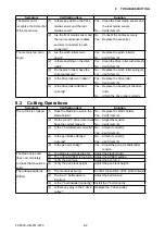
8.3 Cutting Operations
Symptom
Verification item
Solution
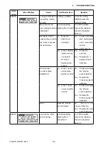
The cut line is crooked. (1) Does the blade turn well in the
blade holder?
No .....Replace the blade holder.
Yes ....Verify item (2).
(2) Do the X and Y drive motor belts
have the correct tension?
No .....Adjust the tension.
No .....Verify item (3).
(3) Is the Y belt attached correctly? No .....Attach it correctly.
Yes ....Verify item (4).
(4) Is the pen block attached
correctly?
No .....Attach it correctly.
Yes ....Verify item (5).
(5) Is the pen arm shaky?
Yes ....Adjust the pen arm shaft slider
tension.
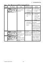
The blade skips and
does not completely
cut lines that should be
solid.
(1)
The blade is extended too far.
Adjust the blade length.
(2) The cutting SPEED is too high. Adjust the SPEED setting.
(3) Verify the pen force.
Adjust the pen force.
(4) Verify the pen block height.
Adjust the pen block height.
The cutting position is
shifted.
(1) The media is skewing.
Confirm the position of the pinch roller(s).
(2) The X or Y belt tension is
incorrect.
Adjust the belt tension.
(3) Is the Y belt installed correctly? Install the Y belt correctly.
(4) Is there any play in the Y drive
pulley?
Replace the Y drive pulley.
Содержание FC8600-100
Страница 1: ...CUTTING PLOTTER SERVICE MANUAL FC8600 60 75 100 130 160 FC8600 UM 251 07 9370 ...
Страница 2: ......
Страница 4: ...FC8600 UM 251 9370 II ...
Страница 32: ......
Страница 103: ...FC8600 UM 251 9370 7 43 7 ADJUSTMENT ...
Страница 118: ...FC8600 UM 251 9370 8 15 8 TROUBLESHOOTING 11 When testing is completed turn off the power to the plotter ...
Страница 124: ...FC8600 UM 251 9370 9 2 9 PARTS LIST Outer Casing 4 6 2 3 9 13 11 12 14 15 10 1 16 8 7 5 ...
Страница 131: ...FC8600 UM 251 9370 9 9 9 PARTS LIST Main Frame 1 3 4 5 7 8 9 10 11 12 6 2 15 16 13 14 20 21 22 17 18 19 ...
Страница 141: ...FC8600 UM 251 9370 10 3 10 BLOCK DIAGRAMS AND CIRCUIT DIAGRAMS 10 2 2 Main Board CONNECTOR ...
Страница 142: ...FC8600 UM 251 9370 10 4 10 BLOCK DIAGRAMS AND CIRCUIT DIAGRAMS 10 2 3 Main Board MOTOR DRIVER ...
Страница 143: ...FC8600 UM 251 9370 10 5 10 BLOCK DIAGRAMS AND CIRCUIT DIAGRAMS 10 2 4 Main Board FPGA ...
Страница 144: ...FC8600 UM 251 9370 10 6 10 BLOCK DIAGRAMS AND CIRCUIT DIAGRAMS 10 2 5 Main Board I F ...
Страница 145: ...FC8600 UM 251 9370 10 7 10 BLOCK DIAGRAMS AND CIRCUIT DIAGRAMS 10 2 6 Main Board MEMORY ...
Страница 146: ...FC8600 UM 251 9370 10 8 10 BLOCK DIAGRAMS AND CIRCUIT DIAGRAMS 10 2 7 Main Board Power When the LAN is connected ...
Страница 147: ...FC8600 UM 251 9370 10 9 10 BLOCK DIAGRAMS AND CIRCUIT DIAGRAMS 10 2 8 LAN Board ...
Страница 148: ...FC8600 UM 251 9370 10 10 10 BLOCK DIAGRAMS AND CIRCUIT DIAGRAMS 10 2 9 Light Pointer ...
Страница 149: ...FC8600 UM 251 9370 10 11 10 BLOCK DIAGRAMS AND CIRCUIT DIAGRAMS 10 2 10Pen Relay Board ...
Страница 151: ...FC8600 UM 251 9370 10 13 10 BLOCK DIAGRAMS AND CIRCUIT DIAGRAMS 10 2 13Control Panel Board ...
Страница 152: ...FC8600 UM 251 9370 10 14 10 BLOCK DIAGRAMS AND CIRCUIT DIAGRAMS 10 2 14Cam Sensor Board ...


