FC8600-UM-251-9370 3-1
3 OPERATIONS
3 OPERATIONS
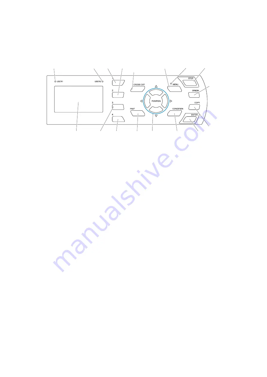
3.1 Control Panel
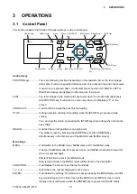
This section explains the function of lamps and keys on the control panel.
USER1 lamp
USER2 lamp
[1] key
[2] key CROSS CUT
key
MENU lamp
[MENU] key
[STOP] key
[ORIGIN] key
[ENTER] key
[CONDITION]
key
POSITION
[FAST] key
[3] key
[4] key
[COPY] key
Screen (LCD)
Control Keys
POSITION keys .............. There are following functions depending on the operation. Move the tool carriage
and media. It will move specified distance when it is pressed once,and continuously
move when it is pressed down. It will select the menu when UP, DOWN, LEFT or
RIGHT arrow keys are displayed in the menu on the screen.
FAST ............................... The tool carriage or the media will move faster when it is pressed simultaneously
with POSITION key. It will work as a menu key when it is displaying “F” on the
screen.
CROSS CUT .................. It will cut off the media that has finished cutting.
STOP .............................. Cutting operation will stop immediately when the [STOP] key is pressed while
cutting.
You can reset the media by pressing the [STOP] key while cutting when the media
has shifted.
ORIGIN ........................... It will set the current position as an origin point.
The plotter is reset by pressing the [ENTER] key and the [ORIGIN] key
simultaneously in the first screen of the MENU mode (MENU screen).
Menu Keys
MENU ............................. It will switch to the MENU mode. MENU lamp is lit in the MENU mode.
It will go into MENU mode if it is pressed once, and MENU mode will be turned off
when it is pressed again.
Different function are set in the MENU mode.
Data received while in the MENU mode will be stored in the data buffer.
CONDITION ................... It will display the screen to set the tool conditions.
1, 2, 3, 4.......................... Select the menu number displayed in the screen.
ENTER ........................... It will define the settings. The plotter is reset by pressing the [ORIGIN] key and this
key simultaneously in the first screen of the MENU mode (MENU screen). It will
display current cutting area when the [ENTER] key is pressed in READY status.
Содержание FC8600-100
Страница 1: ...CUTTING PLOTTER SERVICE MANUAL FC8600 60 75 100 130 160 FC8600 UM 251 07 9370 ...
Страница 2: ......
Страница 4: ...FC8600 UM 251 9370 II ...
Страница 32: ......
Страница 103: ...FC8600 UM 251 9370 7 43 7 ADJUSTMENT ...
Страница 118: ...FC8600 UM 251 9370 8 15 8 TROUBLESHOOTING 11 When testing is completed turn off the power to the plotter ...
Страница 124: ...FC8600 UM 251 9370 9 2 9 PARTS LIST Outer Casing 4 6 2 3 9 13 11 12 14 15 10 1 16 8 7 5 ...
Страница 131: ...FC8600 UM 251 9370 9 9 9 PARTS LIST Main Frame 1 3 4 5 7 8 9 10 11 12 6 2 15 16 13 14 20 21 22 17 18 19 ...
Страница 141: ...FC8600 UM 251 9370 10 3 10 BLOCK DIAGRAMS AND CIRCUIT DIAGRAMS 10 2 2 Main Board CONNECTOR ...
Страница 142: ...FC8600 UM 251 9370 10 4 10 BLOCK DIAGRAMS AND CIRCUIT DIAGRAMS 10 2 3 Main Board MOTOR DRIVER ...
Страница 143: ...FC8600 UM 251 9370 10 5 10 BLOCK DIAGRAMS AND CIRCUIT DIAGRAMS 10 2 4 Main Board FPGA ...
Страница 144: ...FC8600 UM 251 9370 10 6 10 BLOCK DIAGRAMS AND CIRCUIT DIAGRAMS 10 2 5 Main Board I F ...
Страница 145: ...FC8600 UM 251 9370 10 7 10 BLOCK DIAGRAMS AND CIRCUIT DIAGRAMS 10 2 6 Main Board MEMORY ...
Страница 146: ...FC8600 UM 251 9370 10 8 10 BLOCK DIAGRAMS AND CIRCUIT DIAGRAMS 10 2 7 Main Board Power When the LAN is connected ...
Страница 147: ...FC8600 UM 251 9370 10 9 10 BLOCK DIAGRAMS AND CIRCUIT DIAGRAMS 10 2 8 LAN Board ...
Страница 148: ...FC8600 UM 251 9370 10 10 10 BLOCK DIAGRAMS AND CIRCUIT DIAGRAMS 10 2 9 Light Pointer ...
Страница 149: ...FC8600 UM 251 9370 10 11 10 BLOCK DIAGRAMS AND CIRCUIT DIAGRAMS 10 2 10Pen Relay Board ...
Страница 151: ...FC8600 UM 251 9370 10 13 10 BLOCK DIAGRAMS AND CIRCUIT DIAGRAMS 10 2 13Control Panel Board ...
Страница 152: ...FC8600 UM 251 9370 10 14 10 BLOCK DIAGRAMS AND CIRCUIT DIAGRAMS 10 2 14Cam Sensor Board ...

