FC8600-UM-251-9370 3-4
3 OPERATIONS
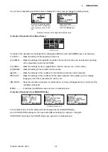
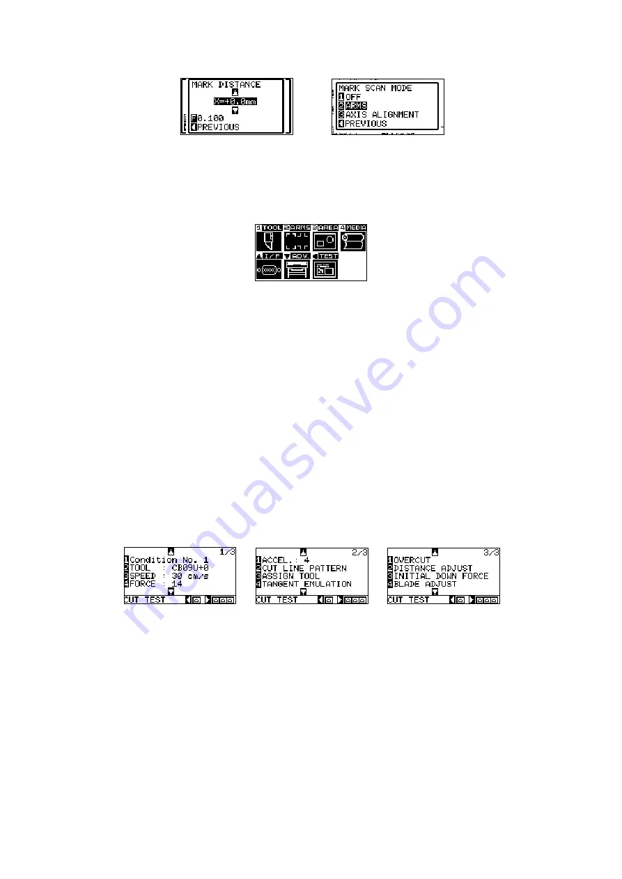
Icon of the corresponding operation button is displayed in the screen to change the setting values.
Increase or decrease the setting
value using POSITION (
pq
) key.
Select the change unit by [FAST]
key.
Select the setting by
number keys (1, 2, 3, 4) or
POSITION (
pqtu
) keys.
Example of screen to change the settings value
Contents of Operation from Menu Screen
MENU screen
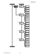
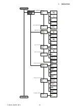
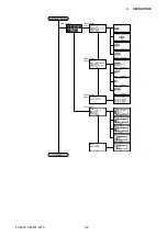
Contents of the operation and settings that is displayed in MENU screen with [MENU] key is as following:
[1] (TOOL): ...... Make the setting for the operation of the tool.
[2] (ARMS): ...... Make the settings and operation to position the tool and media, such as automatic scanning
of the registration marks by the ARMS.
[3] (AREA): ...... Make the settings for area, magnification, rotation, reverse, etc., of the cutting.
[4] (MEDIA): .... Make the setting of the condition for the media.
[
p
] (I/F): .......... Make the settings of the condition for the interfacing with the control computer.
[
q
] (ADV): ....... Make the settings of the conditions for the basic operation of the plotter, such as display
language, unit of the measurements, sensor, etc.
[
t
] (TEST): ...... Does the operation necessary for maintenance, such as self diagnostic test or printout of the
condition settings list.
MENU: ............. It will close the MENU screen and return to default screen.
Contents of Operation from CONDITION Key
CONDITION screen (1-3)
Tool conditions are set in the setting screens displayed by the [CONDITION] key.
Up to 8 CONDITION settings can be saved with different settings in numbers 1 through 8.
CONDITION: It will clear the CONDITION screen and return to default screen.
Содержание FC8600-100
Страница 1: ...CUTTING PLOTTER SERVICE MANUAL FC8600 60 75 100 130 160 FC8600 UM 251 07 9370 ...
Страница 2: ......
Страница 4: ...FC8600 UM 251 9370 II ...
Страница 32: ......
Страница 103: ...FC8600 UM 251 9370 7 43 7 ADJUSTMENT ...
Страница 118: ...FC8600 UM 251 9370 8 15 8 TROUBLESHOOTING 11 When testing is completed turn off the power to the plotter ...
Страница 124: ...FC8600 UM 251 9370 9 2 9 PARTS LIST Outer Casing 4 6 2 3 9 13 11 12 14 15 10 1 16 8 7 5 ...
Страница 131: ...FC8600 UM 251 9370 9 9 9 PARTS LIST Main Frame 1 3 4 5 7 8 9 10 11 12 6 2 15 16 13 14 20 21 22 17 18 19 ...
Страница 141: ...FC8600 UM 251 9370 10 3 10 BLOCK DIAGRAMS AND CIRCUIT DIAGRAMS 10 2 2 Main Board CONNECTOR ...
Страница 142: ...FC8600 UM 251 9370 10 4 10 BLOCK DIAGRAMS AND CIRCUIT DIAGRAMS 10 2 3 Main Board MOTOR DRIVER ...
Страница 143: ...FC8600 UM 251 9370 10 5 10 BLOCK DIAGRAMS AND CIRCUIT DIAGRAMS 10 2 4 Main Board FPGA ...
Страница 144: ...FC8600 UM 251 9370 10 6 10 BLOCK DIAGRAMS AND CIRCUIT DIAGRAMS 10 2 5 Main Board I F ...
Страница 145: ...FC8600 UM 251 9370 10 7 10 BLOCK DIAGRAMS AND CIRCUIT DIAGRAMS 10 2 6 Main Board MEMORY ...
Страница 146: ...FC8600 UM 251 9370 10 8 10 BLOCK DIAGRAMS AND CIRCUIT DIAGRAMS 10 2 7 Main Board Power When the LAN is connected ...
Страница 147: ...FC8600 UM 251 9370 10 9 10 BLOCK DIAGRAMS AND CIRCUIT DIAGRAMS 10 2 8 LAN Board ...
Страница 148: ...FC8600 UM 251 9370 10 10 10 BLOCK DIAGRAMS AND CIRCUIT DIAGRAMS 10 2 9 Light Pointer ...
Страница 149: ...FC8600 UM 251 9370 10 11 10 BLOCK DIAGRAMS AND CIRCUIT DIAGRAMS 10 2 10Pen Relay Board ...
Страница 151: ...FC8600 UM 251 9370 10 13 10 BLOCK DIAGRAMS AND CIRCUIT DIAGRAMS 10 2 13Control Panel Board ...
Страница 152: ...FC8600 UM 251 9370 10 14 10 BLOCK DIAGRAMS AND CIRCUIT DIAGRAMS 10 2 14Cam Sensor Board ...

