background image

– v –

Safety Precautions (Continued)

CAUTION

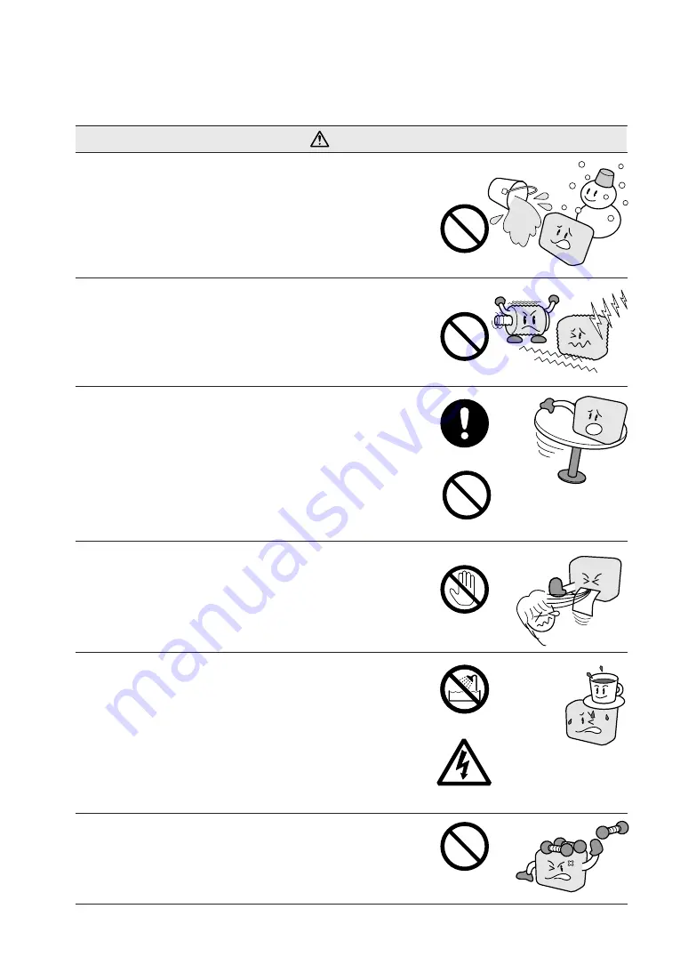
Do not install, use, or store the scanner in a
location that does not meet the specified tempera-
ture and humidity ranges.

• Such location may impair the scanner’s perform-

ance and cause the scanner to malfunction or break
down.

Do not install, use, or store the scanner in a
location subject to excessive mechanical vibra-
tion or electrical noise.

• Such location may impair the scanner’s perform-

ance and cause the scanner to malfunction or break
down.

Do not install the scanner on an unstable surface.

• The scanner could break due to impact from falling

from the surface or cause injury to the operator.

While the scanner is operating (reading or ejecting
a document), keep hands, clothing, and other
objects away from the document.

• Injury could result from an object getting tangled in

the scanner’s rollers.

Do not place any receptacle containing water or
other fluid on top of the scanner.

• Fluid falling inside the scanner may cause a fire

hazard or electrical shock due to a short circuit or
overheating.

Do not place heavy objects on the scanner.

• Such action may impair the scanner’s performance

due to deformation or other damage, and cause the
scanner to malfunction or break down.

Prohibited

Avoid water areas

Beware of electrical shock

Prohibited

Keep away

Prohibited

Install on a level surface

Prohibited

Содержание CS1000EV

Страница 1: ...CS1000EV 1100EV USER S MANUAL MANUAL NO CS1000 UM 153 COLOR IMAGE SCANNER...

Страница 2: ...ategory provides information that if ignored is highly likely to cause fatal or serious injury to the operator This category provides information that if ignored is likely to cause fatal or serious in...

Страница 3: ...e scanner is damaged from being dropped or other impact turn off its power and unplug its power cord from the electrical socket Use of the scanner in such status may result in a fire hazard or electri...

Страница 4: ...g the scanner with its power plug incompletely inserted into the electrical socket could cause a fire hazard or electrical shock Do not allow dust or metallic matter to adhere to the power cord s plug...

Страница 5: ...ock Be sure to hold the power cord s plug or the interface cable s con nector Before disconnecting the power cord or SCSI interface cable be sure to turn off the scanner Failure to do so may damage th...

Страница 6: ...pact from falling from the surface or cause injury to the operator While the scanner is operating reading or ejecting a document keep hands clothing and other objects away from the document Injury cou...

Страница 7: ...mpair the scanner s performance and cause the scanner to malfunction or break down Such action may cause a fire hazard or electrical shock due to a short circuit or overheating Do not clean the scanne...

Страница 8: ...use Please be sure to observe them strictly Notes Regarding This Manual All rights reserved No part of this publication may be reproduced stored in a retrieval system or transmitted in any form or by...

Страница 9: ...sheet from the bottom of the document hold down unit Please refer to Section 4 5 Removing the Document Hold Down Unit and Section 4 6 Mounting the Document Hold Down Unit of this manual for the remov...

Страница 10: ...SI Cable 3 3 3 4 Setting the ID Number 3 5 3 5 Turning the Scanner On or Off 3 6 3 6 Connecting the Scanner to a Computer 3 7 3 7 Checking the Interface Connection 3 16 3 8 Installing the Scanning Mas...

Страница 11: ...nning Image Data Becomes Black or White 6 3 6 7 The Image Quality Has Dropped 6 3 6 8 The Input Image Data Is Incorrectly Aligned 6 4 6 9 Smudges Not Appearing in the Original Document Appear in the S...

Страница 12: ...00 mm CS1000EV or to 630 mm CS1100EV Compatible with document sizes from ISO A4 up to ANSI E CS1000EV or ANSI D CS1100EV Capable of color and grayscale scanning Capable of scanning in color 8 bit colo...

Страница 13: ...se promptly contact your sales representative or nearest Graphtec vendor Standard Accessories Power cable 1 Carrier sheet IS0907 CS1000EV 1 or IS0908 CS1100EV CS1000 Series User Guide CD ROM 1 CS1000...

Страница 14: ...and before mounting the scanner unit Eight bolts and an Allen wrench are provided with the stand 1 Using four bolts loosely attach the center bar 3 to side stay R 1 and side stay L 2 1 2 3 Attach the...

Страница 15: ...e scanner or to the person doing the installation Always hold the scanner by the side covers Side cover Positioning pin Side cover 3 Fully tighten the four bolts on the center bar to secure the side s...

Страница 16: ...n unit to be removed Cover sensor This senses whether the top cover is open or closed and interrupts scanner operation if the top cover is opened during operation Stand The stand unit is assembled for...

Страница 17: ...r Flashing Flashes red when a document is detected during the self test when the scanner is turned on or when the scanning is suspended by pressing the STOP key Unlit Normal status FORWARD key Advance...

Страница 18: ...line inlet SCSI connectors SCSI ID switches Used to specify the ID numbers of the SCSI interfaces DIP switch Used to set the scanner s functions Power switch Controls the on off status of the power s...

Страница 19: ...support wires regardless of the type of document being scanned CS1100EV Document support wires If you are using the CS1100EV model make sure that the document support wires are attached before beginni...

Страница 20: ...port wire and insert the other end 3 Press down on both sides of the document support wire 4 Attach the other document support wires in the same manner Detach the document support wires when moving or...

Страница 21: ...old down unit in the box in which it came Stock brackets EV Document hold down unit How to attach the stock brackets CS1000EV CS1100EV model mounted on the optional stand 1 Hook the two stock brackets...

Страница 22: ...e Monitor 1024 768 pixels High Color or higher resolution SCSI board by Adaptec PCI type For 8 bit color data CPU Pentium III 866 MHz or higher Memory 512 MB or more Monitor 1024 768 pixels True Color...

Страница 23: ...le plug into an electrical socket supplying AC voltage Check that the scanner s Power switch remains in the Off position until the connection of both the power cord and SCSI interface cable has been c...

Страница 24: ...SCSI interface board Daisy chain A method for connecting peripheral devices in a ring arrangement The use of an incompatible cable may cause the scanner to malfunction or damage the interface If the c...

Страница 25: ...ble Cable clamp 3 Insert the cable s other end into the computer s connector 4 If this scanner will be a terminal within the network configuration set Bit 4 of the DIP switch on the scanner s rear pan...

Страница 26: ...ber that corresponds to the host computer s applications 2 3 2 1 The ID can be set from 0 to 7 The scanner s default ID number is 2 If the host computer cannot communicate with the scanner first check...

Страница 27: ...and ERROR lamps on the control panel light up When the scanner has been initialized the POWER lamp lights up If you have a CS1100EV model please refer to Section 2 2 Part Names and Functions page 2 5...

Страница 28: ...ed in the computer Connecting the CS1000EV CS1100EV to a Computer for the First Time For Windows 95 or Windows 95 Version a the actual screen displayed may be different from the one shown depending on...

Страница 29: ...the computer are properly connected via the SCSI interface cable turn on the scanner first and then turn on the computer 2 When Windows 95 has been booted the window below appears 3 Click the Next but...

Страница 30: ...anner and the computer are properly connected via the SCSI interface cable turn on the scanner first and then turn on the computer 2 When Windows 98 has been booted the window below appears 3 Click th...

Страница 31: ...O OPERATE THE SCANNER 5 Remove the check marks from all boxes and then click the Next button 6 Click the Next button 7 Click the Finish button 8 The Windows 98 Desktop appears and the CS1000EV CS1100E...

Страница 32: ...ow is displayed 3 Click on Next to search for the driver 4 Upon completion of the search for the driver the window shown below is displayed Click on the Finish button 5 The Windows Me desktop is displ...

Страница 33: ...connecting the CS1000EV CS1100EV to the computer turn on the CS1000EV CS1100EV and then turn on the computer 2 When Windows 2000 boots the message below appears 3 Next the Found New Hardware Wizard a...

Страница 34: ...es menu shown below 6 Click the Next button to start searching for the driver files 7 When the wizard has finished its search the menu below appears Insert a check in the Disable the device box then c...

Страница 35: ...1 Connect the scanner to the computer turn on the scanner first and then turn on the computer 2 When Windows XP starts up the following window appears 3 Next the Found New Hardware Wizard window appea...

Страница 36: ...CANNER 5 Once the computer finds the driver the following window appears Turn on the Don t prompt me again to install this software check box Then click the Finish button 6 The Windows XP desktop appe...

Страница 37: ...he SCSI adapter instruction manual For Windows 95 98 Me Open the System window from within the Control Panel in My Computer Click on the Device Manager tab to display the list of installed devices Con...

Страница 38: ...the Device Manager button to display a list of the installed devices Check that the scanner is acknowledged by the computer under Other devices For Windows XP Select Control Panel from the Start Menu...

Страница 39: ...Series User Guide CD ROM containing the OPS112 program files into the computer s CD ROM drive 3 Click the Taskbar s Start button then click the Run icon 4 Enter the CD ROM drive name and OPS112 DISK1...

Страница 40: ...e CD ROM containing the OPS116 program files into the computer s CD ROM drive 3 Click the Taskbar s Start button then click the Run icon 4 Enter the CD ROM drive name and OPS116 DISK1 SETUP EXE as the...

Страница 41: ...3 20 CS1000EV 1100EV 3 PREPARING TO OPERATE THE SCANNER...

Страница 42: ...1 mm 1189 mm E 34 in 44 in CS1100EV Documents with a maximum width of 630 mm Size ISO Size ANSI A4 210 mm 297 mm A 8 5 in 11 in A3 297 mm 420 mm B 11 in 17 in A2 420 mm 594 mm C 17 in 22 in A1 594 mm...

Страница 43: ...ng points when scanning a thick medium The CS1000EV CS1100EV cannot scan a document that is thicker than 1 5 mm When using the carrier sheet ensure that the combined thickness of both the document and...

Страница 44: ...ay time after the document is inserted to automatically advance the document to the initial position for scanning The rollers start rotating when the FORWARD switch is pressed on the control panel aft...

Страница 45: ...g downward Do not place anything other than the document to be scanned on the scanning table as the scanner rollers may start rotating which is extremely dangerous The document may not be fed in corre...

Страница 46: ...roperly advanced to the initial position of scanning because the target document is folded wrinkled or otherwise hard to load in the scanner To scan transparent or translucent documents As shown in th...

Страница 47: ...nner The EV document hold down unit has a stronger hold down force than that of the standard unit and may cause damage to thin documents Use the carrier sheet when scanning film documents or similar I...

Страница 48: ...nt Hold Down Unit To clean the scanner you must first remove the document hold down unit It is also necessary to remove the document hold down unit to remove a jammed document Procedure 1 Turn off the...

Страница 49: ...unit in order to lift the document hold down unit up and off 4 With its bottom surface facing the side place the removed document hold down unit on a stable surface Underside Scanning may be affected...

Страница 50: ...is physically possible to mount it with its right and left sides reversed Because the scanner s precision has been adjusted before shipment from the factory however its reading precision will decreas...

Страница 51: ...4 10 CS1000EV 1100EV 4 LOADING A DOCUMENT...

Страница 52: ...clean the image sensors whenever necessary Procedure 1 Turn off the scanner 2 Remove the document hold down unit as described in Section 4 5 Removing the Document Hold Down Unit 3 As shown below wipe...

Страница 53: ...h the glass scanning table is not a maintenance part that requires periodic replacement it is a consumable part because its surface may receive slight scratches due to minute particles of dust and oth...

Страница 54: ...on the paper sensors may prevent the document from being detected The sensors must be cleaned when necessary 1 Turn off the scanner 2 Open the top cover holding it in the center 3 Wipe the two paper s...

Страница 55: ...nt hold down unit as described in Section 4 5 Removing the Document Hold Down Unit 3 Wipe clean the underside of the document hold down unit see below using a soft cloth that has been soaked in water...

Страница 56: ...ation immediately turn off the scanner remove the document hold down unit and then remove the jammed document Procedure 1 Turn off the scanner 2 Remove the document hold down unit as described in Sect...

Страница 57: ...CE 4 If the document is jammed at the rear remove the document from the inside by pulling it toward the rear 5 Reattach the document hold down unit as described in Section 4 6 Attaching the Document H...

Страница 58: ...ed The calibration sheet is a paper product Do not attempt to clean it with any type of liquid cleaner The calibration sheet is a consumable item Replacement sheets can be purchased from your sales re...

Страница 59: ...e scanner while calibration is underway Accidentally switching off the scanner may result in damage that requires servicing 1 Connect the scanner to the computer Switch on the scanner then switch on t...

Страница 60: ...o the scanner as instructed 12 Click the OK button to start scanning The scanned data is displayed when scanning is complete Colors may differ slightly for individual sensors to make it easier to iden...

Страница 61: ...ks Areas that have been selected shown in blue can be deselected by clicking the left mouse button again To deselect all selected areas click the Clear button 16 Once all required areas have been spec...

Страница 62: ...computer and or the scanner lock into place The SCSI adapter used is not compatible Change the SCSI transfer rate Maximum Sync with high speed data transfer SCSI 3 or Transfer Rate to 10 MB s For deta...

Страница 63: ...Install EZ SCSI provided with the SCSI adapter For details refer to the SCSI adapter instruction manual For Windows 2000 XP If EZ SCSI is provided with the SCSI adapter EZ SCSI provided with the SCSI...

Страница 64: ...EV document hold down Replace the EV hold down unit with the unit when you should be using the standard standard unit or place the document in the hold down unit for a thin document carrier sheet prov...

Страница 65: ...nning Master 21 driver provided with your page 6 5 scanner select the Joint Adjustment function then perform adjustment to achieve a seamless image Your scanner comes shipped from the factory after be...

Страница 66: ...scanning table Control panel side Sensor 2 Sensor 1 Joint between sensors 4 5 Joint between sensors 3 4 Joint between sensors 2 3 Joint between sensors 1 2 A2 8 5 8 5 A2 Image sensor position Example...

Страница 67: ...ned The document scanned was creased Creased or curled documents should be or curled scanned by placing them inside the carrier sheet provided 6 11 The Document Length Differs from the Scanned Data Le...

Страница 68: ...Code Item name OPS115 KIT E Software to upgrade OPS112 Scanning Master 21 to OPS115 Scanning Master Pro Color PG0010 Media basket for the CS1000EV model ST0038 Stand with media basket for the CS1100EV...

Страница 69: ...A 2 CS1000EV 1100EV APPENDIX A OPTIONAL AND MISCELLANEOUS ITEMS...

Страница 70: ...56 colors Light source LED RGB Interface SCSI 2 Rated power supply 100 to 120 200 to 240 VAC 10 50 60 Hz Operating environment Temperature 10 C to 35 C Humidity 35 to 80 RH no condensation Power consu...

Страница 71: ...6 colors Light source LED RGB Interface SCSI 2 Rated power supply 100 to 120 200 to 240 VAC 10 50 60 Hz Operating environment Temperature 10 C to 35 C Humidity 35 to 80 RH no condensation Power consum...

Страница 72: ...CS1000EV 1100EV C 1 APPENDIX C EXTERNAL VIEW APPENDIX C EXTERNAL VIEW External Dimensions of the CS1000EV 156 1020 1205 600 Unit mm Dimensional precision error 5 mm...

Страница 73: ...C 2 CS1000EV 1100EV APPENDIX C EXTERNAL VIEW External Dimensions of the CS1100EV 169 850 426 381 When mounted on the optional stand 156 1020 850 600 640 Unit mm Dimensional precision error 5 mm...

Страница 74: ...es 4 1 Document width 4 1 E ERROR LED 2 4 6 2 EV Document hold down unit 2 8 4 6 F FORWARD key 2 4 H Host computer connecting to the 3 7 I ID number setting 3 5 Image sensors cleaning the 5 1 Interfac...

Страница 75: ...The specifications etc in this manual are subject to change without notice CS1000 UM 153 February 27 2003 1st edition 01 GRAPHTEC CORPORATION...

Отзывы: