29
2. Carefully clean out any dust and fluff from within the vacuum unit enclosure. In particular ensure that
the air inlet to the vacuum motor is clear. Refer to figure 7-4.
3. Check the vacuum unit cover, remove any dust and fluff from the inner surfaces taking care not to
damage the acoustic lining. Check that the inlet grille in the top surface is clear.
5. Check the condition of the pressure switch tube.
6. Replace the vacuum unit cover using the reverse of the removal procedure.
IMPORTANT: Ensure that the ‘in-line’ connection of the earth wire is remade before fitting the cover. Refer
to Figure 7-3.
7.2 Auger Unit
1. Isolate the electrical supply to the auger motor using the remote isolator mounted on the auger unit.
Set the isolator to OFF and lock it off.
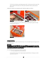
2. Unscrew and remove the two domed nuts and remove the galvanised steel cover from the auger unit.
Refer to Figure 7-5.
3. Inspect the suction chamber through the glass panel. Check for any signs of blockage that could
interfere with the operation of the auger. Refer to Figure 7-6.
4. If necessary, unscrew and remove the two nuts and remove the top cover from the suction chamber.
Check the seal on the underside of the cover. When replacing the cover ensure that it is correctly fitted
before tightening the nuts.
7.3 Flexible Pellet Tubes
1. Where possible, check along the entire length of both flexible pellet tubes for any signs of damage or
wear – either internal or external and any signs of blockage. Rectify as necessary.
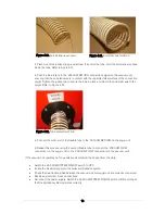
2. Check that BOTH pellet tubes are securely connected to the spigot connectors at BOTH ends, i.e. at
the vacuum unit and at the auger unit. Check that the anti-static wire is in contact with the unpainted steel
surface of the connection spigot. Refer to Section 4.3 for details.
3. If necessary, tighten the ‘jubilee’ hose clip to secure the tube in place and clamp the anti-static wire to
the spigot. Refer to Figure 4-22.
Figure 7-6.
Suction chamber window
Figure 7-5. Auger unit with cover
Domed nuts
Содержание WPVKIT10
Страница 12: ...12 Figure 3 6 SpiraVac operation flow diagram ...
Страница 22: ...22 Figure 5 4 Vacuum unit wiring diagram ...
Страница 24: ...24 Figure 5 6 Heating system controls S plan type system connection diagram ...
Страница 25: ...25 Figure 5 7 Heating system controls Y plan type system connection diagram ...


