9
3.3 Flexible Pellet Tubes
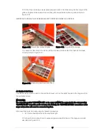
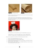
Two lengths of flexible tube (supplied with the SpiraVac system kit) are used to connect the vacuum unit
(on the top of the pellet hopper) to the auger unit (mounted on the bulk pellet store).
The tube supplied is a 50mm diameter reinforced Polyurethane flexible tube with a copper anti-static wire
moulded into the tube wall. When fitting the tube, this wire must be exposed and placed in contact with
the steel connections (on the vacuum and auger units) at each end. Refer to Section 5.3 for details.
The maximum length of tube between the vacuum and auger units is 20 metres (i.e. 2 x 20 metres lengths
- one each way). The maximum rise over that length is 5 metres. No reduction in this maximum allowance
is required for any changes in the height of the tube over the length of run.
Both tubes are secured at each end, to the connections on the vacuum and auger units, using the four
hose clips provided with the kit. Refer to Section 4.3 for details.
Any pellet tubes run against walls MUST be adequately supported at no more that 1 metre centres, and
at either sides of a bend in the tube, using the 50mm metal pipe clips provided.
3.4 Operating Sequences
The vacuum unit has a ‘VACUUM SYSTEM’ ON/OFF switch on the control panel.
•
When this switch is set to ON – the vacuum system operates in Automatic mode. Refer to
Section 3.4.1 below.
•
When this switch is set to OFF – the vacuum system operates in Manual mode. Refer to Section
3.4.2 below
3.4.1 Automatic Mode
With the VACUUM SYSTEM switch is set to ON the SpiraVac vacuum system is operational.
In this condition the SpiraVac can function in one of two different automatic operating modes:
•
‘Top-up’ mode – to automatically top-up the hopper when the weight of pellets in the pellet
hopper falls below the minimum level, as detected by the contents diaphragm switch. Once the
contents switch is activated, the vacuum motor and filling process will automatically start, as
detailed below.
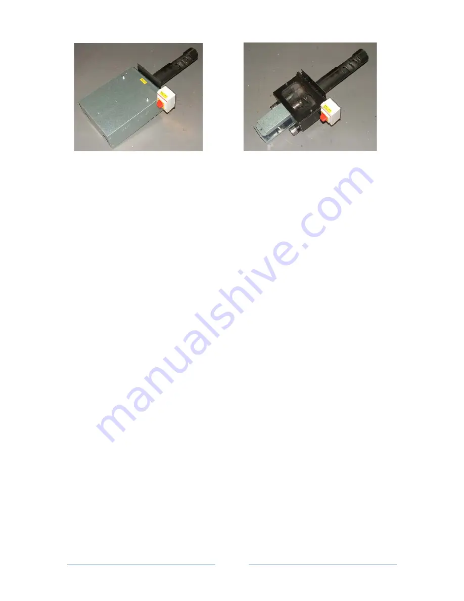
Figure 3-5. Auger unit with cover removed
Figure 3-4. Auger unit with cover fitted
Содержание WPVKIT10
Страница 12: ...12 Figure 3 6 SpiraVac operation flow diagram ...
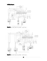
Страница 22: ...22 Figure 5 4 Vacuum unit wiring diagram ...
Страница 24: ...24 Figure 5 6 Heating system controls S plan type system connection diagram ...
Страница 25: ...25 Figure 5 7 Heating system controls Y plan type system connection diagram ...


