


28
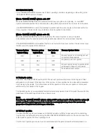
7. Servicing
IMPORTANT Before commencing any service work on the Grant SpiraVac system, ensure that the
electrical supply from the pellet hopper is isolated, as follows:
•
Set the ‘VACUUM SYSTEM’ switch on the SpiraVac control panel to OFF.
•
Disconnect the 6-way connector between the pellet hopper and the vacuum unit.
This will enable the boiler to be left operating whilst the SpiraVac system is serviced.
On completion of the service work, re-connect the electrical supply from the pellet hopper using the
reverse of the above procedure.
7.1 Vacuum Unit
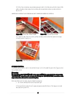
1. Remove the cover from the vacuum unit, as follows:
•
Unscrew and remove the four upper outer screws at the rear of the vacuum unit. Refer to Figure
7-1.
IMPORTANT Do NOT remove the four screws at the bottom rear of the vacuum unit.
•
Slacken off the four screws – two on each side, at the bottom of the cover sides. Refer to Figure
7-2.
•
Carefully lift the cover up and off the vacuum unit taking care to disconnect ‘in-line’ connection in
the earth wire before completely removing the cover from the vacuum unit. Refer to Figure 7-3.
Figure 7-4. Vacuum unit without cover
Figure 7-1. Cover fixing screws - rear
Figure 7-2. Cover fixing screws - sides
Figure 7-3. Earth wire connector
Vacuum motor air inlet
Remove these
four screws
l
Loosen these
two screws on
both sides
Содержание WPVKIT10
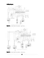
Страница 12: ...12 Figure 3 6 SpiraVac operation flow diagram ...
Страница 22: ...22 Figure 5 4 Vacuum unit wiring diagram ...
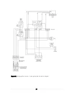
Страница 24: ...24 Figure 5 6 Heating system controls S plan type system connection diagram ...
Страница 25: ...25 Figure 5 7 Heating system controls Y plan type system connection diagram ...


