


16
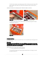
7. Unscrew and remove the three screws and nuts holding the pellet deflector channel inside the
rear of the hopper. Take care not to drop the small nuts into the hopper!
Remove the
deflector channel from the hopper and replace the screws and nuts to block off the
holes. Refer to Figure 4-13.
8. Re-fit the top panel (complete with vacuum unit) back on top of the hopper. Secure top panel
using the four screws previously removed. Refer to Figure 4-14.
NOTE: THIS IS A JOB FOR TWO PERSONS AS THE VACUUM UNIT IS HEAVY!
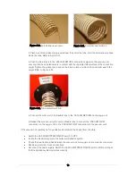
9. Open the hinged door on top of the pellet hopper and rest it against the front of the vacuum
unit. To prevent the door from dropping closed whilst fitting the pellet dam plate, secure it to the
vacuum unit using duct tape or similar.
10. Fit the pellet dam plate into the hopper with the bracket (on the back of the plate) facing
toward the back of the hopper and the three fixing holes at the top. Refer to Figure 4-15.
Fix the pellet dam plate in place using three screws (previously removed) in the corresponding
holes along the front edge of the hopper rear top panel. Refer to Figure 4-16.
NOTE: Do not tighten these three screws but leave them with about 2 - 3mm of thread showing.
11. Insert the grille into the hopper opening (with the door stay opening to the left). Align and
engage the three ‘keyhole’ slots (in the rear edge of the grille) with the three corresponding grille
fixing screws on the front edge of the hopper rear top panel. Refer to Figure 4-17.
Figure 4-13. Pellet deflector channel
Figure 4-14. Vacuum unit on hopper
Figure 4-15. Pellet dam plate
Figure 4-16. Pellet dam plate fixings
Содержание WPVKIT10
Страница 12: ...12 Figure 3 6 SpiraVac operation flow diagram ...
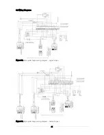
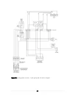
Страница 22: ...22 Figure 5 4 Vacuum unit wiring diagram ...
Страница 24: ...24 Figure 5 6 Heating system controls S plan type system connection diagram ...
Страница 25: ...25 Figure 5 7 Heating system controls Y plan type system connection diagram ...