Grandaire WFAR Series Скачать руководство пользователя страница 19

440 04 7113 02

19

Specifications subject to change without notice.

FIRE OR EXPLOSION HAZARD

Failure to follow this warning could result in personal

injury, death, and/or property damage.
Never purge a gas line into a combustion chamber.

Never test for gas leaks with an open flame. Use a

commercially

available

soap

solution

made

specifically for the detection of leaks to check all

connections. A fire or explosion may result causing

property damage, personal injury or loss of life.

!

WARNING

14. Check for gas leaks with a commercially available

soap solution made specifically for the detection of

leaks.

15. Turn gas on at electric switch on gas valve and at

external shut-off or meter

16. Turn power on at external disconnect, fuse or circuit

breaker.

17. Run the furnace through two complete heating cycles

to check for proper operation

18. Install control door when complete.

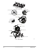
Servicing Hot Surface Igniter

The igniter does

NOT

require annual inspection. Check

igniter resistance before removal. Refer to Fig. 8, 9 and 14.

1. Turn off gas and electrical supplies to furnace.

2. Remove control door.

3. Disconnect igniter wire connection.

4. Check igniter resistance. Igniter resistance is affected

by temperature. Only check resistance when the

igniter is at room temperature.
a. Using an ohm meter, check resistance across both

igniter leads in connector.

b. Cold reading should be between 40 ohms and 70

ohms.

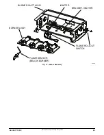
5. Remove igniter assembly.

a. Using a 1/4--in. driver, remove the two screws

securing the igniter mounting bracket to the burner

assembly (See Fig. 14 .)

b. Carefully withdraw the igniter and bracket assembly

through the front of the burner assembly without

striking the igniter on surrounding parts.

c. Inspect igniter for signs of damage or failure.

d. If replacement is required, remove the screw that

secures the igniter on igniter bracket and remove the

igniter.

6. To replace igniter and bracket assembly, reverse

items 5a through 5d.

7. Reconnect igniter harness to the igniter, dressing the

igniter wires to ensure there is no tension on the

igniter itself. (See Fig. 14.)

8. Turn on gas and electrical supplies to furnace.
9. Verify igniter operation by initiating control board self--

test feature or by cycling thermostat.

10. Replace control door.

Flushing Collector Box and Drainage System

ELECTRICAL SHOCK AND FIRE HAZARD

Failure to follow this warning could result in personal

injury, death, and/or property damage.
Turn off the gas and electrical supplies to the furnace

and install lockout tag before performing any

maintenance or service. Follow the operating

instructions on the label attached to the furnace.

!

WARNING

1. Turn off gas and electrical supplies to furnace.

2. Remove control door.

3. Disconnect pressure switch tube from pressure

switch port.

NOTE

: Ensure the pressure switch tube disconnected from

the pressure switch is higher than the collector box opening
or water will flow out of tube.

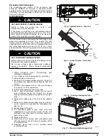
4. Remove the collector box plug from the top port on

the upper corner of the collector box. (See Fig. 10)

5. Attach a funnel with a flexible tube to port on the

collector box.

6. Flush inside of collector box with water until discharge

water from condensate trap is clean and runs freely.

7. Repeat steps 4 thru 6 with middle plug on upper

corner of collector box.

8. Remove the pressure switch tube from the collector

box.

NOTE

: Do

NOT

blow into tube with tube connected to the

pressure switch.

9. Clean pressure switch port on collect box with a small

wire. Shake any water out of pressure switch tube.

10. Reconnect tube to pressure switch and pressure

switch port.

11. Remove the relief tube from the port on the collector

box and the trap.

12. Clean the relief port on collect box and the trap with a

small wire. Shake any water out of the tube.

13. Reconnect relief tube to trap and collector box ports.

Cleaning Condensate Drain and Trap

NOTE

: If the condensate trap is removed, a new gasket

between the trap and collector box is required. Verify a
condensate trap gasket is included in the service kit or
obtain one from your local distributor.

1. Disconnect power at external disconnect, fuse or

circuit breaker.

2. Turn off gas at external shut-off or gas meter.

3. Remove control door and set aside.

4. Turn electric switch on gas valve to OFF.

5. Disconnect external drain from condensate drain

elbow or drain extension pipe inside the furnace and

set aside.

6. Disconnect the condensate trap relief hose from

collector box port and condensate trap.

NOTE

: If condensate has a heat pad attached to the trap,

trace the wires for the pad back to the connection point and
disconnect the wires for the heat pad.

7. Remove the screw that secures the condensate trap

to the collector box, remove the trap and set aside.

8. Remove the trap gasket from the collector box if it did

not come off when the trap was removed.

9. Discard the old trap gasket.

10. Rinse condensate trap in warm water until trap is

clean.

Содержание WFAR Series

Страница 1: ...nual in the following manner CAUTION Signal Words on Product Labeling Signal words are used in combination with colors and or pictures or product labels The signal word WARNING is used throughout this...

Страница 2: ...eath WARNING signifies hazards which could result in personal injury or death CAUTION is used to identify unsafe practices which may result in minor personal injury or product and property damage NOTE...

Страница 3: ...1 115vac terminal is energized whenever blower operates HUM 24vac terminal is only energized when the low pressure switch LPS is closed on a call for heat Prime Condensate Trap with Water CARBON MONO...

Страница 4: ...ns to match the required orifice to the manifold pressure to the heat content and specific gravity of the gas To do this 1 Obtain average yearly gas heat value at installed altitude from local gas sup...

Страница 5: ...ld be clear blue almost transparent See Fig 12 i Remove jumper R to W j Reinstall manifold pressure tap plug from gas valve 2 Verify natural gas input rate by clocking meter NOTE Contact your HVAC dis...

Страница 6: ...e S Shortened furnace life S Component damage Temperature rise must be within limits specified on furnace rating plate Recommended operation is at midpoint of rise range or slightly above CAUTION Jump...

Страница 7: ...thermostat per thermostat instructions and install on sub base or wall 5 Install blower access door Electronic thermostat Set cycle rate for 3 cycles per hr Check Safety Controls The flame sensor gas...

Страница 8: ...0 2743 3048 18 20 0 81 Derate multiplier factors are based on midpoint altitude for altitude range ON OFF Switch Regulator Seal Cap Regulator Adjustment Regulator Seal Cap under Cap 1 2 NPT Outlet 1 8...

Страница 9: ...290 22 164 327 818 64 56 112 281 23 157 313 783 66 54 109 273 24 150 300 750 68 53 106 265 25 144 288 720 70 51 103 257 26 138 277 692 72 50 100 250 27 133 267 667 74 48 97 243 28 129 257 643 76 47 9...

Страница 10: ...10 440 04 7113 02 Specifications subject to change without notice 338309 201 Rev E A11602 Fig 5 Service Label Information...

Страница 11: ...2 42 3 3 42 3 4 915 825 43 3 6 43 3 7 43 3 8 42 3 2 850 44 3 8 43 3 5 43 3 6 43 3 7 875 44 3 6 44 3 7 43 3 4 43 3 5 4000 900 44 3 4 44 3 5 44 3 7 44 3 8 1219 925 44 3 2 44 3 4 44 3 5 44 3 6 950 44 3...

Страница 12: ...4 2134 700 43 3 5 43 3 7 43 3 8 42 3 2 725 44 3 8 43 3 4 43 3 5 43 3 6 750 44 3 5 44 3 7 44 3 8 43 3 4 8000 775 44 3 3 44 3 4 44 3 5 44 3 7 2438 800 44 3 1 44 3 2 44 3 3 44 3 4 825 44 2 9 44 3 0 44 3...

Страница 13: ...0 1110 1100 1090 1065 1035 990 935 870 805 Red 3 2 0 433 940 920 910 890 865 830 790 745 690 625 100C048C SIDE BOTTOM Black 4 0 373 1715 1660 1610 1555 1490 1420 1340 1245 1150 1065 Yellow 3 3 5 379 1...

Страница 14: ...ECTRICAL SHOCK HAZARD Failure to follow this warning could result in personal injury or death There may be more than one electrical supply to the furnace Check accessories and cooling unit for additio...

Страница 15: ...s shown If any of the original wire as supplied must be replaced use same type or equivalent wire W Y GND THERMOSTAT TERMINALS 1 2 3 A11387 Fig 7 Typical Single Stage Wiring Diagram Component Self Tes...

Страница 16: ...ene cigarette lighter fluid dry cleaning fluids or other volatile fluids 3 Paint thinners and other painting compounds paper bags or other paper products Exposure to these materials could lead to corr...

Страница 17: ...wer compartment Disconnect the vent and combustion air pipe by a Loosen the clamps on the vent couplings and combustion air pipe external to the furnace b Separate the pipes from the couplings and mov...

Страница 18: ...hut off or gas meter 3 Remove control door and set aside 4 Turn electric switch on gas valve to OFF 5 Disconnect the gas pipe from gas valve and remove pipe from the furnace casing 6 Remove individual...

Страница 19: ...ng could result in personal injury death and or property damage Turn off the gas and electrical supplies to the furnace and install lockout tag before performing any maintenance or service Follow the...

Страница 20: ...a problem exists which needs to be corrected such as improper adjustment of manifold pressure insufficient or poor quality combustion air improper vent termination incorrect size or damaged manifold...

Страница 21: ...may occur CAUTION 1 Obtain propylene glycol RV swimming pool antifreeze or equivalent 2 Turn off gas and electrical supplies to your furnace 3 Remove furnace control door 4 Remove the top unused rubbe...

Страница 22: ...Fig 12 Burner Flame SET SCREW MOTOR WHEEL HUB MOTOR SHAFT FLAT SCREW MOTOR ARM GROMMET SCREW LOCATION BLO HSG ASSY BRACKET BRACKET ENGAGEMENT SEE DETAIL A CAPACITOR OR POWER CHOKE WHEN USED BRACKET SC...

Страница 23: ...440 04 7113 02 23 Specifications subject to change without notice FLAME SENSOR BELOW BURNER FLAME ROLLOUT SWITCH BRACKET IGNITER IGNITER BURNER SUPT ASSY BURNER ASSY A11403 Fig 14 Burner Assembly...

Страница 24: ...If the burner flame is proven the blower motor is energized on HEAT speed 25 sec after the gas valve GV is energized Simultaneously the electronic air cleaner terminal EAC 1 is energized and remains e...

Страница 25: ...flash the status code of the previous fault or status code 11 1 short and 1 long flash if there was no previous fault After the control repeats the code 4 times the control will go through a brief co...

Страница 26: ...control will repeat the ignition sequence 3 more times before lockout 14 occurs If flame signal is lost during the blower on delay period blower will come on for the selected blower off delay Check t...

Страница 27: ...440 04 7113 02 27 Specifications subject to change without notice 339236 2 Rev A Fig 16 Wiring Diagram...

Страница 28: ...on service or maintenance can cause personal injury property damage or death Consult a qualified installer service agency or your local gas supplier for information or assistance The qualified install...

Отзывы: