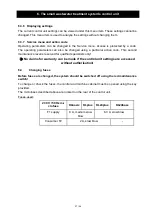
6. The small wastewater treatment system's control unit
20 / 54
KLbasic/KL24base control unit
KLplus/KL24plus control unit
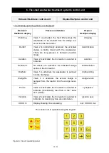
The following operating phases are displayed:
KLbasic /
KL24base display
Process undertaken
KLplus /
KL24plus display
Charchng
Valve 1 is activated, the feed lifter pumps the
wastewater to be cleaned from the sludge res-
ervoir into the bio reactor.
charging
Denitrif
Valve 2 is intermittently activated, the activated
sludge is briefly mixed with the wastewater.
There are long pauses in between (reaction
times).
denitrification
Aeration
Valve 2 is activated, the bio reactor is aerated at
intervals.
aeration
Sediment
No valves are activated, the activated sludge
settles in the bio reactor.
sedimentation
Discharc
Valve 1 is activated, the wastewater is pumped
into the discharge.
discharching
SludgeRe
Valve 4 is activated, the excess sludge is
pumped from the reactor into the sludge reser-
voir.
sludge return
Pause
Valve 2 is activated, the bio reactor is aerated at
intervals (considerably less than in the "aera-
tion" phase).
cyclepause
Vacation
Valve 2 is activated, the bio reactor is aerated at
intervals, no cleaning cycles are undertaken.
vacation oper.
XX.XX m
Display showing time remaining.
rest: XXX.XX min
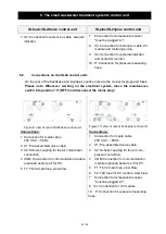
The control unit is operated using the keypad.
Figure 6: View of operating panel


