background image

308620

12

Pressure Relief Procedure

WARNING

INJECTION HAZARD

The system pressure must be manually
relieved to prevent the system from
starting or spraying accidentally. Fluid

under high pressure can be injected through the
skin and cause serious injury. To reduce the risk of
an injury from injection, splashing fluid, or moving
parts, follow the 

Pressure Relief Procedure

whenever you:

D

are instructed to relieve the pressure,

D

stop spraying,

D

check or service any of the system equipment,

D

install or clean the spray tip.

1.  Engage the gun safety latch.
2.  Turn the engine switch to OFF.
3.  Move the pressure control ON/OFF switch to OFF.
4.

Disengage the gun safety latch. Hold a metal part
of the gun firmly to a grounded metal pail. Trigger
the gun to relieve pressure.

5.  Engage the gun safety latch.
6.  Open the pressure drain valve. Leave the pressure

drain valve open until you are ready to spray
again.

7.  Disconnect the spark plug cable.
If you suspect that the spray tip or hose is completely
clogged, or that pressure has not been fully relieved
after following the steps above,


VERY SLOWLY

loosen the tip guard retaining nut or hose end coupling
to Relieve the pressure gradually, then loosen com-
pletely. Now clear the tip or hose.
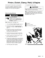
Flushing

When to Flush

1.

New Sprayer. This sprayer was factory tested in
lightweight oil,which was left in to protect the pump
parts.

Before using water–base paint, 

flush with mineral

spirits, followed by a soapy water flush, and then a
clean water flush.

Before using oil–base paint, 

flush with mineral

spirits.

2.

Changing Colors. Flush with a compatible solvent
such as mineral spirits or water.

3.

Changing from water–base to oil–base paint.


Flush

with warm, soapy water, then mineral spirits.

4.

Changing from oil–base to water–base paint.


Flush

with mineral spirits, followed by warm, soapy
water, and then a clean water flush.

CAUTION

To prevent pump corrosion or damage to pump
components, never leave water or any type of paint
in the sprayer when it is not in use. Pump the water
or the paint out with mineral spirits.

5.

Storage.

Water base paint: 

flush with water, then mineral

spirits and leave the pump, hose and gun filled
with mineral spirits. Shut off the sprayer, remove
the spark plug cable, and open the pressure drain
valve to Relieve the pressure. Leave the drain
valve open.

Oil base paint: 

flush with mineral spirits and leave

the pump, hose and gun filled with mineral spirits.
Shut off the sprayer, remove the spark plug cable,
and open the pressure drain valve to Relieve the
pressure. Leave the drain valve open.

6.

Startup after storage.

Before using water–base paint

, flush out the

mineral spirits with soapy water, and then with
clean water.

When using oil–based paint, 

flush out the mineral

spirits with the paint to be sprayed.

Содержание 231363

Страница 1: ... HandTitet Tip Guard and 517 size SwitchTipt Model 231550 Series B Basic Sprayer with Lo Boy Cart Model 231552 Same as 231550 with hose and gun RACr X HandTitet Tip Guard and 517 size SwitchTipt CAUTION Always use a minimum hose length of 50 foot 15 m 1 4 inch ID or 50 foot 15 m 3 8 inch ID An undersized hose may result in poor equipment performance and damage to the clutch GRACO INC P O BOX 1441 ...

Страница 2: ... is for professional use only D Read all instruction manuals tags and labels before operating the equipment D Use the equipment only for its intended purpose If you are not sure call your distributor D Do not alter or modify this equipment Use only genuine Graco parts D Check equipment daily Repair or replace worn or damaged parts immediately D Do not exceed the maximum working pressure of the low...

Страница 3: ...hecking or servicing the equipment D Tighten all fluid connections before operating the equipment D Check the hoses tubes and couplings daily Replace worn or damaged parts immediately Do not repair high pressure couplings you must replace the entire hose D Fluid hoses must have spring guards on both ends to help protect them from rupture caused by kinks or bends near the couplings TOXIC FLUID HAZA...

Страница 4: ...nt follow the Pressure Relief Procedure on page 12 to prevent the equipment from starting unexpectedly Liquids can be injected into the body by high pressure airless spray or leaks especially hose leaks Keep body clear of the nozzle Never stop leaks with any part of the body Drain all pressure before removing parts Avoid accidental triggering of gun by always setting safety latch when not spraying...

Страница 5: ...air gasoline mixture for cold starting J Throttle Adjusts engine speed for large or small orifice spray tips K Engine Switch Enables disables engine operation L Fluid Outlet Hose and spray gun are connected here M Pressure Control Controls clutch cycling to maintain fluid pressure N Engine 4 0 HP gasoline engine P Clutch Transfers power from engine to drive assembly R Drive Assembly Transfers powe...

Страница 6: ...not use thread sealant and do not install the spray tip yet WARNING If you supply your own hoses and spray gun be sure the hoses are electrically conductive that the gun has a tip guard and that each part is rated for at least 3000 psi 210 bar 21 MPa Maximum Working Pressure This is to reduce the risk of serious injury caused by static sparking fluid injection or over pressurization and rupture of...

Страница 7: ...ater and then flush with clean water b Before using oil base paint flush with mineral spirits only c See Flushing on page 13 for the flushing procedure 7 Prepare the paint according to the manufacturer s recommendations a Remove any skin that may have formed b Stir the paint to mix the pigments c Strain the paint through a fine nylon mesh bag available at most paint dealers to remove the particles...

Страница 8: ...ber of 91 or higher Unleaded fuel minimizes the combustion chamber deposits 2 Gasolines containing alcohol gasohol Do not use gasohol which contains methanol if the gaso hol does not contain cosolvents and corrosion inhibitors for methanol Even if it does contain such additives do not use the gasohol if it contains more than 5 methanol or 10 ethanol NOTE The Honda engine warranty does not cover th...

Страница 9: ... to start the engine when it is pressurized could damage the recoil system 4 Move the pressure control switch to OFF 5 To start the engine a Turn the pressure adjusting knob all the way counterclockwise to the lowest pressure set ting b Slide the metal throttle lever away from the fuel tank to maximum position fully left c If the engine is cold close the choke by mov ing the gray lever d If the en...

Страница 10: ... safety g Move the pressure control switch to OFF h Relieve pressure by opening the pressure drain valve i Close the pressure drain valve WARNING INJECTION HAZARD To reduce the risk of serious injury from fluid injection never operate the spray gun with the tip guard removed 9 Install the spray tip in the gun See the separate tip instruction manual 308 644 supplied 10 Move the pressure control swi...

Страница 11: ...E FIRST 20 HOURS OF OPERATION Drain the oil and refill with clean oil WEEKLY Remove the cover of the air filter and clean the element Replace the element if necessary If operating in an unusually dusty environment check the filter daily and replace it if necessary Replacement elements may be purchased from your local Honda dealer WEEKLY Check the level of the TSL in the displace ment pump packing ...

Страница 12: ...ayer was factory tested in lightweight oil which was left in to protect the pump parts Before using water base paint flush with mineral spirits followed by a soapy water flush and then a clean water flush Before using oil base paint flush with mineral spirits 2 Changing Colors Flush with a compatible solvent such as mineral spirits or water 3 Changing from water base to oil base paint Flush with w...

Страница 13: ...rom the gun WARNING FIRE AND EXPLOSION HAZARD To reduce static sparking and splashing always remove the spray tip from the gun and hold a metal part of the gun firmly to the side of a grounded metal pail when flushing 6 Follow Startup on page 9 Keep the gun trig gered until clean solvent comes from the nozzle Release the trigger and lock the gun trigger safety CAUTION Operation with the pump not p...

Страница 14: ...ayer upright to avoid oil seepage The engine operates but the displacement pump does not The pressure control switch is turned off Turn on the switch displacement pump does not operate The pressure setting is too low Turn the pressure adjusting knob clockwise to increase pressure The fluid filter 21 is dirty Clean the filter See page 13 The tip or the tip filter is clogged Clean the tip or the tip...

Страница 15: ...Clean the screen The pressure setting is too low Increase the pressure See Step 11 page 10 The engine speed is too low Increase the throttle setting See Step 11 page 10 The fluid filter 21 the tip filter or the tip is clogged or dirty Clean the filter See page 13 Or see the gun instruction manual There is a large pressure drop in the hose Use a larger diameter hose Fluid is spitting from the gun T...

Страница 16: ...o not lose the thrust balls 6a and 2d or let them fall between the gears which will damage the drive housing if not removed The balls which are heavily covered with grease usually stay in the housing recesses but could be dislodged If the balls are not in place the bearings will wear prematurely 6 Remove and inspect the crankshaft 8 and the connecting rod 10 Installation 7 Lubricate the inside of ...

Страница 17: ...que to 100 in lb 11 N m 3 2 Quantity of three Quantity of one Lubricate with SAE non detergent oil 4 16 15 10 9 25 6 16 5 8 3 65 6a 2d A 26 23 REF A 19 68 1 1 2 3 4 2 69 64 06003 Fig 6 Brush G n lubricant and recoat with bearing grease Pack with bearing grease 0 22 pint ...

Страница 18: ...b and tip the pressure control 25 forward and up to detach it from the drive housing 6 4 Guide the harness A through the pinion housing and drive housing and remove the pressure con trol 5 Guide the harness of the new pressure control through the drive housing and pinion housing passages 6 Install the new pressure control Tip the pressure control down and back into the drive housing 6 Do not pinch...

Страница 19: ...ING INJECTION HAZARD To reduce the risk of serious injury whenever you are instructed to relieve pressure follow the Pressure Relief Procedure on page 12 1 Relieve pressure 2 Remove the junction box screws 65 and lock washers and remove the junction box 63 3 Remove the ring 314 and rubber boot 315 4 Disconnect the red wires from the ON OFF switch and remove the switch 5 Install the switch so the i...

Страница 20: ... page 31 2 Use a pull twist motion to remove the transducer 22 from the pump manifold 3 Clean paint residue from the hole in the manifold do not scratch the surface of the hole 4 Lightly apply oil to the o ring of the new transducer 5 Install the transducer in the pump manifold while guiding the o ring and backup ring into place 6 Align the holes in the transducer as shown by the arrows in Fig 9 7...

Страница 21: ...l engage and the hose will separate from the tube 3 Replace the o ring 110 if it is worn or damaged 4 Lubricate the o ring 110 and the inlet tube 40 threads with light grease 5 Align the suction hose coupling with the threads of the inlet tube 40 Tighten the hose onto the tube at least 4 turns to ensure that the threads have disen gaged and can function as a swivel joint CAUTION Misalignment or cr...

Страница 22: ...at 43b pry out the gasket NOTE Whenever the gasket 43a is removed re place it with a new one 3 Coat the o ring 43d with grease Press the stem into the valve body Install the spring washers and spring retainer into the valve body 4 Place the seat 43b in the valve body so the lapped side is toward the ball Apply a small amount of grease to the new gasket 43a and install it in the valve body NOTE The...

Страница 23: ...ers 16 4 Pull the pinion housing 2 away from the clutch housing 1 The armature 51b will come with it 5 Pull the armature 51b off the hub 2h of the pinion housing Also see Fig 13 6 If replacing the complete pinion housing assembly 2 brush G n lubricant supplied on the pinion shaft teeth Then recoat the pinion shaft teeth with bearing grease supplied Pack the remaining bearing grease in the bottom p...

Страница 24: ...o to Reassembly page 29 Step 7 or continue on page 24 If you purchased parts separately follow steps 1 to 9 below Disassemble only as far as needed for the parts being replaced NOTE The old bearing 2g will be damaged as it is removed Have one on hand if you need to remove it for any reason Always replace bearing 2g if installing a new hub 2h 1 To replace small bearing 2n or roller clutch 2m press ...

Страница 25: ...prevent the partially disas sembled sprayer from falling over 3 Pull the drive assembly D away from the clutch housing 1 4 The armature 51b will move with the drive as sembly Remove the armature from the pinion hub 2h CAUTION Examine the splined hub 2h Fig 13 page 24 for wear Replace as needed Follow the Pinion Housing instructions page 24 5 There are two ways to remove the rotor 51a a Remove the ...

Страница 26: ...tion 1 Working under the mounting plate A remove the two lock nuts 78 and then pull the screws 77 out of the base of the engine Remove the screw 61 Disconnect the red wire B from the engine lead D Disconnect the black and white wires from the field Pull the cable E carefully through the grommet 50 before removing the engine See Fig 16 and 17 2 Lift the engine carefully and place it on a work bench...

Страница 27: ...g screws are required to remove the clamp NOTE Refer to Fig 19 1 Loosen the two screws 57 on the clamp 55 working through the slot at the bottom of the clutch housing 1 2 Install two screws B of the tool A in two of the threaded holes in the clamp 55 Tighten the screw C until the clamp comes off 3 Skip ahead to Reassembly page 28 Step 2 or continue below 05840 Fig 19 1 55 57 C B A Clutch Housing N...

Страница 28: ...urate measuring device to measure the distance between the bar and the face of the clamp Adjust the clamp as necessary Torque the two screws 57 to 120 in lb 14 N m 4 Connect the wires of the harness D with the screws 79 in both places on the field wires can be attached to either connection Pull the plastic caps C up and snap them over the screws Install the field in the clutch housing Push the wir...

Страница 29: ...the cart to prevent the sprayer from falling over 5 Place the engine 48 assembly on the cart Align the mounting holes Carefully guide the engine wire and wiring harness E from the field through the appropriate grommets 50 in the mounting plate A Install the flange screws 77 and lock nuts 78 Install the screw 61 Tighten all three screws Connect the engine wire to the red wire B and connect the blac...

Страница 30: ... of the armature facing the rotor 51a slide the armature onto the hub 2h in the drive pinion assembly D just until the chamfered end of the hub 2h protrudes through the armature See Detail B Fig 23 There will be significant resis tance Attach the cardboard spacer supplied with the clutch kit to the face of the armature Bend tabs over outside diameter of armature Brace the cart against a wall to ke...

Страница 31: ...e clean the transducer see page 20 when ever you repack the pump Replace these parts as need ed Removing the pump See Fig 24 1 Flush the pump if possible Relieve pressure Stop the pump with the piston rod 107 in its lowest position if possible 2 Remove the filter 21 3 Remove suction hose or tube 40 For suction hose refer to page 21 NOTE If repairing only the intake valve assembly go to Intake valv...

Страница 32: ...n These parts could be projected into the air and result in serious injury or property damage including the pump connecting rod or drive housing 2 Align the hole in the rod 107 with the connecting rod assembly 10 Use a screwdriver to push the retaining spring 12 up and push in the pin 11 Push the retaining spring 12 into place around the connecting rod 3 Reconnect the suction and drain hoses Insta...

Страница 33: ...dge 1 311 238676 CONDUCTOR electrical 1 312 191242 PLATE module 1 313 105679 SWITCH toggle 1 314 105658 RING locking 1 315 105659 BOOT toggle 1 316 238791 CONDUCTOR electrical 1 Included in Repair Kit No 238661 Y Replacement Danger and Warning labels tags and cards are available free Parts Drawing Pressure Control 71 06002 37 65 313 312 310 316 315 1 To pressure control switch 1 314 311 303 304 30...

Страница 34: ...51a 83 55 1 79 35 36 DETAIL 29 74 75 76 73 50 28 48 78 38 49 2 90 1 61 22 31 See page 38 for the parts 34 47 23 9 59 58 40 30 6a 19 8b 18 17 21 20 8a 16 7 24 20 11 10 32 33 12 43 57 16 44 45 46 6 3 15 16 26 63 65 68 69 54 56 80 81 16 2d 2 84 77 13 14 25 64 8 85 3 1 27 1 89 37 37 66 67 1 1 92 91 3 05846D ...

Страница 35: ...drain 1 43d 168110 O RING 1 43e 224968 STEM valve drain 1 43f 111599 WASHER flat 1 43g 187623 SPRING compression 1 43h 187622 RETAINER spring valve 1 44 224807 BASE valve 1 45 111600 PIN grooved 3 32 x 1 1 46 187625 HANDLE drain valve 1 47 100721 PLUG pipe headless 1 4 18 nptf 1 48 108879 ENGINE gasoline 1 49 239422 CART 1 50 109099 BUSHING snap 2 51 238798 CLUTCH ASSEMBLY 1 51a ROTOR clutch 1 51b...

Страница 36: ...3 26 17 40 39 20 65 44 43 REF 32 REF 31 6 24 67 27 68 9 6a 16 45 38 49 47 21 20 63 110 See page 38 for parts DETAIL 29 74 75 76 73 50 28 48 2 80 81 77 35 36 90 34 1 3 2 Label See the detail above 3 2 79 78 61 57 16 53 57 51b 51a 16 16 83 55 1 59 58 54 56 84 64 85 31 3 1 1 37 1 37 89 66 1 1 109 25 1 92 91 3 05980D ...

Страница 37: ... 1 43f 111599 WASHER flat 1 43g 187623 SPRING compression 1 43h 187622 RETAINER spring valve 1 44 224807 BASE valve 1 45 111600 PIN grooved 3 32 x 1 1 46 187625 HANDLE drain valve 1 47 100721 PLUG pipe headless 1 4 18 nptf 1 48 108879 ENGINE gasoline 1 49 238685 CART 1 50 109099 BUSHING snap 2 51 238798 CLUTCH ASSEMBLY 1 51a ROTOR clutch 1 51b ARMATURE clutch 1 53 238803 FIELD clutch 1 54 108800 P...

Страница 38: ... ends 1 204 246220 CONTRACTOR II SPRAY GUN Includes RACr X HandTitet Tip Guard and 517 size SwitchTipt See 309639 for parts 1 204 203 202 0160 Pinion Assembly Parts List and Drawing Assembly 238684 Ref No Part No Description Qty Ref No Part No Description Qty 2a 191208 PINION HOUSING 1 2b 105489 PIN 2 2c 102873 BEARING 1 2d 100069 BALL 1 2e 107394 BEARING 1 2f 185916 PINION SHAFT 1 2g 109002 BALL ...

Страница 39: ...r 21 MPa Noise level Sound power 102 dB A per ISO 3744 Sound pressure 87 dB A Measured at 3 1 feet 1 m under maximum operating conditions Cycles gallon liter 540 142 Maximum delivery 0 62 gpm 2 35 liter min Fuel tank capacity 0 66 gallons 2 5 liter Maximum tip size 0 025 2000 psi 137 bar 13 7 MPa with latex Inlet paint strainer 12 mesh stainless steel screen reusable Outlet paint filter 60 mesh 25...

Страница 40: ... limited to incidental or consequential damages for lost profits lost sales injury to person or property or any other incidental or consequential loss shall be available Any action for breach of warranty must be brought within two 2 years of the date of sale GRACO MAKES NO WARRANTY AND DISCLAIMS ALL IMPLIED WARRANTIES OF MERCHANTABILITY AND FITNESS FOR A PARTICULAR PURPOSE IN CONNECTION WITH ACCES...

Отзывы: