


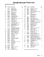

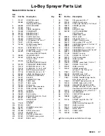


308620
28
Reassembly
CAUTION
The sprayer will be out of balance when only the
engine and clutch housing are installed. Support the
rear of the cart to prevent the sprayer from falling
over.
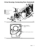
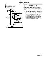
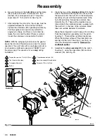
1.
Install the
clutch housing (1)
, capscrews (83) and
lockwashers (84) on the engine. Use special
alignment tool to position clutch housing on en-
gine. Torque screws (83) to 200 in-lb (22 N
m).
2.
Install the engine shaft
key (56).
See Fig. 21.
3.
Press the
clamp (55)
onto the engine shaft (A).
Maintain the 1.41 inch
0.01 (35.8
0.25 mm)
dimension shown in Fig. 22.
To check the dimension, place a rigid, straight
steel bar (B) across the face of the clutch housing
(1). Use an accurate measuring device to measure
the distance between the bar and the face of the
clamp. Adjust the clamp as necessary. Torque the
two screws (57) to 120 in–lb (14 N.m).
4.
Connect the wires of the harness (D) with the
screws (79) in both places on the field (wires can
be attached to either connection). Pull the plastic
caps (C) up and snap them over the screws. Install
the field in the clutch housing. Push the wire
harness through the slot in the clutch housing.
Align the setscrew holes in the field and the clutch
housing (1). Hand tighten the setscrews (58)
oppositely and evenly. See Fig. 21.
05842A
Fig. 21
53
55
83
84
1
56
79
D
57
A
C
58
1
2
Torque the screws oppositely and
evenly to 25 in–lb (2.8 N
@
m).
Slot.
2
1
3
Torque the screws to 200 in–lb (22
N
@
m).
3
4
Apply low strength thread locker to set
screws (58).
4
0
5
5
Torque the screws to 120 in–lb (14 N
@
m).