


308620
35
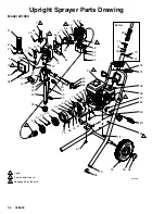
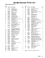
Upright Sprayer Parts List
Model 231363, Series A
Ref.
No.
Part No.
Description
Qty.
Ref.
No.
Part No.
Description
Qty.
1
191207
HOUSING, clutch
1
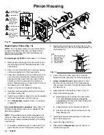
2
238684
HOUSING, pinion
1
See page 38 for parts
6
238691
DRIVE HOUSING
1
6a
100069
BALL
1
7
176904
LABEL, designation
1
8
235558
CRANKSHAFT
1
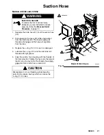
8a
180131
BEARING, thrust
1
8b
107434
BEARING, thrust
1
9
187789
COVER, front, blue
1
10
218359
CONNECTING ROD
1
11
176818
PIN, headless, 3/8” dia. x 1”
1
12
176817
SPRING, retaining
1
13
112777
SCREW, mach, ovl hd, 10–24 x .375
2
14
190321
HANGER, pail
1
15
103345
SCREW, socket head,
3
1/4–20 x 1–1/4”
16
105510
LOCKWASHER, 1/4”
16
17
111706
CAPSCREW, 7/16–14 x 1–3/4”
2
18
235699
PUMP, displacement
1
See manual 308190 for parts
19
238802
GEAR REDUCER
1
20
162453
NIPPLE, hex, 1/4 npsm x
2
1/4 npt, 1–3/16”
21
239425
FILTER, fluid
1
See Manual 308249 for parts
22
235009
PRESSURE TRANSDUCER
1
23
114415
SCREW, filh, 8–32 x 1–1/4”
1
24
114416
SCREW, filh, 10–24 x 1–5/8”
2
25
238799
SWITCH, pressure control
1
26
111705
SCREW, filh, 8–32 x 2–1/2”
3
27
290364
LABEL, identification, front
1
28
238187
HANDLE & HOSE RACK
1
29
192027
SLEEVE
2
30
108982
CONNECTOR, tube
1
31
181102
CLIP, spring
1
32
186549
DRAIN TUBE
1
33
186245
CLIP, spring
1
34
106062
WHEEL, semi–pneumatic
2
35
101242
RING, retaining, wheel
2
36
104811
HUBCAP
2
37
100020
WASHER
4
38
108691
PLUG, tubing
2
39
183770
STRAINER, inlet, 1/2–14 npsm
1
40
192169
TUBE, suction
1
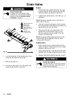
43
235014
DRAIN VALVE
1
See Fig.11
43a
111699
GASKET
1
43b
187615
SEAT
1
43c
187621
HOUSING, valve, drain
1
43d
168110
O-RING
1
43e
224968
STEM, valve, drain
1
43f
111599
WASHER, flat
1
43g
187623
SPRING, compression
1
43h
187622
RETAINER, spring, valve
1
44
224807
BASE, valve
1
45
111600
PIN, grooved, 3/32 x 1”
1
46
187625
HANDLE, drain valve
1
47
100721
PLUG, pipe, headless, 1/4–18 nptf
1
48
108879
ENGINE, gasoline
1
49
239422
CART
1
50
109099
BUSHING, snap
2
51
238798
CLUTCH ASSEMBLY
1
51a
ROTOR, clutch
1
51b
ARMATURE, clutch
1
53
238803
FIELD, clutch
1
54
108800
PIN, dowel, 5/16 x 1”
1
55
188426
CLAMP, mounting, rotor
1
56
183401
KEY, parallel, 3/16” sq x 7/8”
1
57
108803
CAPSCREW, hex sch, 1/4–28 x 1.0”
6
58
108801
SETCREW, 1/4”
4
59
100644
CAPSCREW, sch, 1/4–20 x 3/4”
5
61
113802
CAPSCREW, hex hd, 3/8–16 x 5/8”
1
63
238672
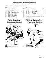
PRESSURE CONTROL
1
64
191258
GASKET, housing
1
65
111703
SCREW, filh, 10–24 x 3”
4
66
189919
PLATE, designation
1
67
290228
LABEL, caution
1
68
187963
GASKET
1
69
100643
SCREW, socket head, 1/4–20 x 1”
2
71
110637
SCREW, 10–24 X 3/8”
1
72
290061
LABEL, warning
1
73
109032
SCREW, recess pnh,
self–tap “F”, No. 10–24 x 1/4”
4
74
112827
BUTTON, snap
2
75
183350
WASHER, plain, 0.90”
2
76
108068
PIN, spring, straight, 3/16”
2
77
110837
SCREW, serrated flange, hex hd,
5/16–18 unc–2a x 1.5”
2
78
110838
LOCKNUT, heavy hex, 5/16–18
3
79
109033
SCREW, bdgh, 6–32 x 3/16”
2
80
237686
GROUNDING CLAMP & WIRE
1
81
112798
SCREW, mach thd, 1/4–20 x 0.375
1
See Pressure Control Parts, page 33
83
109031
CAPSCREW,1/2 sch, 5/16–24 x 1”
4
84
104008
LOCKWASHER
4
85
221183
CONDUCTOR, electrical
1
86
108868
CLAMP, wire
1
See Fig. 16
87
101344
SCREW, cap, 5/16–18 x 7/8”
1
See Fig. 16
89
LABEL, warning, See page 39
1
90
181867
LABEL, warning
1
91
192014
PLATE, indicator
1
92
113684
RIVET, blind
2
Y
Extra warning labels available free of charge.


