JSV3H
OM−05229
PAGE D − 3
TROUBLESHOOTING
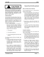
Refer to the wiring diagram(s) accompany-
ing the motor and control box before re-
connecting any electrical leads which have
been disconnected. Connections to the
wrong terminals may damage the motor
and/or control devices.
Voltage Imbalance
Use a voltmeter to read each phase of the incom-
ing 3-phase power. Each phase must balance with
the other two as closely as can be measured with a
commercial instrument. If the phases are out of
balance, contact your power company. If the
phases are balanced, check out the motor as de-
scribed in the following steps:
a. Use a voltmeter, Amprobe, or equivalent in-
strument to read the voltage of incoming
power lines 1 and 2, 2 and 3, and 1 and 3 at the
control box. Voltage must match as closely as
can be measured. If possible, measure the
voltage at the control box with:
1. The pump off.
2. The pump running in air.
3. The pump submerged and running under
full load.
The voltage measured under each condition must
be the same.
b. If voltage is balanced when the pump is off but
is imbalanced when the pump is running,
thoroughly check the power source, all inter-
connecting cables, and the pump motor to
isolate the defect.
c. Use an Amprobe or equivalent instrument to
measure the current draw (amperage) of
each phase while the pump is running under
full load, and with no load. In each condition,
the amperage readings for all three phases
must match as closely as can be measured.
Normal amperage values are listed in Table 1,
Section B; these values apply only when the
voltage at the site is the normal voltage listed.
Motor and Power Cable Continuity
Set the megohmmeter at R x 1 scale and zero-
balance it. Test as follows:
a. Shut off incoming power to the control box,
and disconnect the motor power cable leads.
Connect the megohmmeter test leads to any
two power cable leads, and note the megohm
meter reading. A high resistance reading indi-
cates an open or broken circuit in the power
cable or motor windings, or a bad connection
between the motor and cable.
b. Repeat Step a. with each set of leads. The
three readings shall be as close as can be
measured.
c. If readings indicate that continuity problems
exist in the motor or motor cable, the motor
must be returned to the factory or to a U/L-ap-
proved facility.
Insulation Resistance
Set the megohmmeter at R x 100, and zero-ba-
lance it. Test as follows:
a. Shut off incoming power to the control box,
and disconnect the motor power cable leads.
Connect one megohmmeter test lead to the
motor cable green/yellow ground lead. Touch
the other test lead to each of the motor cable
leads in turn. Note the readings.
b. Readings will indicate resistance values in
both the power cable and motor windings.If
resistance reads infinity (
1
), insulation is
good. If resistance reads between infinity (
1
),
and 1 megohm, insulation is acceptable but
should be rechecked regularly. If resistance
reads less than 1 megohm, insulation should
be checked more closely and frequently.
c. If readings indicate that a ground exists, test
the stator and motor power cable separately.
Replace as required.

