


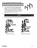


STEP 4 - RUNWAY OR MONORAIL INSTALLATION
Runway or Monorail to Header Weldment Connections
4.1
Suspend runway section under installed support
structure (refer to enclosed
General Arrangement
Drawing
for recommended dimensions and runway
or monorail location).
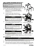
4.2
Using spine clamp angles, clamp plates, and
hardware provided, attach runway or monorail
section to header weldment, as shown in
diagram
4A
or
4B
.
4.3
Check to make sure that runway is level (/-
1/8”) and parallel to opposite runway (/- 1/4”)
over a 20’-0” distance.
4.4
Tighten hanger hardware to full compression of
lockwasher, do not exceed 50 ft.-lbs.
4.5
If you
DO NOT
have additional runways or monorails
to install, proceed to Step 4.13 on page 8 otherwise proceed to Step 4.6 on page 8.
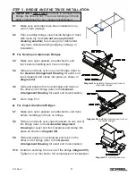
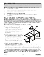
Splice Joint Instructions
IMPORTANT:
To install additional runway sections, runways must be spliced together.
4.6
Attach hardware to splice joint. Slide splice joint over track portion of installed runway.
4.7
Lift next runway section into position for splicing to previously installed runway, bringing runway
ends together. Maximum gap between ends of load carrying flanges shall be less than or equal to
1/16” (1.5mm). Center lower splice joint over the two track ends (
diagram 4C
or
4D
, page 8).
WARNING
Do not deviate from the bridge “span” dimension
shown on the General Arrangement Drawing.
Bridge “span” is the distance between runways
(centerline to centerline).
IMPORTANT:
Keep in mind that splice joints must be
within 48” of hanger center.
IMPORTANT:
The closer the runways are to parallel
the easier the bridge is to move.
Diagram 4A.
Attaching runway to header
weldment (standard hangers).
7
9/18 Rev C
Diagram 4B.
Attaching runway to header
weldment (3-hole hangers).
WARNING
There must be a minimum of two threads showing
at both ends of the threaded rod.
WARNING
If 3-hole hangers are being used, one threaded
rod must be secured through the runway top tube.
Failure to do so may result in the runway falling to
the floor.
WARNING
Do not deviate from the dimensions specified in the General Arrangement Drawing for maximum
space from header center to splice joint. Typically 48” maximum.