

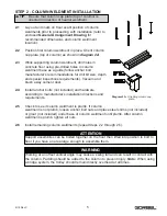

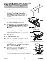


STEP 5 - BRIDGE AND END TRUCK INSTALLATION
5.1
Make sure end stops have been installed in one
end of both runways.
5.2
Prior to adding bridge, clean inside flanges of track
with clean dry cloth (
do not use any kind of
cleaning solution
) to remove grit or debris that
may have collected during shipping, storage, or
installation.
For Non-Coped Aluminum Bridges
5.3
Make sure nylon spacers are attached to end
truck before installing end truck on bridge.
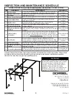
5.4
Slide an end truck over one end of bridge (refer to
the
General Arrangement Drawing
for exact end
truck location) and clamp into place, as shown in
diagram 5A
.
5.5
Slide and position the non-clamping end truck on
the other end of bridge (refer to the
General
Arrangement Drawing
for exact end truck location).
5.6
Go to Step 5.10.
For Coped Aluminum Bridges
5.7
Make sure nylon spacers are attached to end truck
before installing end truck on bridge.
5.8
Slide an end truck over coped brackets on one end of
the bridge (refer to the
General Arrangement
Drawing
for exact end truck location) and clamp into
place as shown in
diagram 5B
.
5.9
Slide and position non-clamping end truck on the
other end of bridge (refer to the
General
Arrangement Drawing
for exact end truck location).
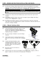
5.10
Install an end stop to one end of the bridge (
diagram 5C
).
Tighten nut on thru bolt to full compression of lockwasher.
IMPORTANT:
ONLY ONE
end truck is clamped to the
bridge: the other is not. The non-clamping end truck
allows adjustment for any runway misalignment.
Diagram 5A.
Installing clamping end truck on
Aluminum bridges.
Diagram 5B.
Installing clamping end truck on
Aluminum bridges,
9
9/18 Rev C
Diagram 5C.
Installing end stop.


