WIRE ROPE REPLACEMENT INSTRUCTIONS (CONTINUED)
Removal of Existing Wire Rope (Continued):
18.
From the limit switches is a gray colored lead that plugs into the circuit
board. Its connected location is approximately two inches down the right
side of the circuit board labeled “limits”. Gently pull out the plug lead to
disconnect plug from board (
diagram O
).
19.
Using 13mm open-end wrench, loosen, not remove, the two flange nuts
and remove reinforcement bracket.
20.
Using a 4mm hex wrench, remove four M5 socket head cap screws that
fasten the swiveling circuit board bracket to the front support plate. Two
screws are located on the top and two are on the bottom of bracket. Set
screws in plastic front cover. Swing bracket out towards you and to the left
(
diagrams P
and
Q
).
21.
For 330 lb. (150kg) and 660 lb. (300kg) units only:
Using 13mm open-end
wrench, loosen, not remove, the two flange nuts and remove
reinforcement bracket (
diagram Q
).
22.
Using an M5mm hex wrench, remove two M6 socket head cap screws
from the drum gates. Slide the unthreaded gate out towards you. Place
gate and hardware in front cover (
diagram R
).
23.
Using a n M6mm hex wrench, remove the two M8 socket head cap
screws from the blue colored rope retainer and slide retainer off of rope
end towards you. Set retainer and screws in front cover (
diagram S
).
24.
Grasp wire rope with right hand where it exits actuator. Keep rope from
bending while pushing rope upward to unseat the stop sleeve from the
anchor channel. If this does not work, use a medium screwdriver (flat)
sliding it upward between rope and drum to progressively pry rope out of
anchor channel while still pushing up on rope. Remove rope from
actuator through opening at bottom once unseated.
Diagram O.
Gently press tab and pull out the
grey limit switch wiring lead to
disconnect plug from board.
Top
Bottom
Diagram R.
Remove two M6 socket head cap
screws from the drum gates.
Diagram S.
Remove the two M8 socket head
cap screws and slide retainer
off of rope end towards you.
Limit Switch
Wiring Lead
Limit Switch
Plug
Diagram Q.
Loosen flange nuts
Diagram P.
Remove (4) M5 SHCS (2 on top
and 2 on bottom) that fasten the
swiveling PCB bracket to the
front support plate.
Drum Gate
Cap Screws
Rope Retainer
Cap Screws
55
Содержание G-Force iQ2 1320 lb
Страница 44: ...PROGRAM MODE CONTINUED 44...
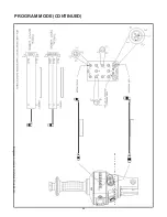
Страница 46: ...PROGRAM MODE CONTINUED Diagram K Handle IO Detail Pendant Model 46...
Страница 85: ...Figure 9 VNC Viewer App 85...

