background image

WIRE ROPE REPLACEMENT INSTRUCTION (CONTINUED)


Installation of New Wire Rope:


1.  Grasp anchor end of rope (not thimble) and make a crimp in gloved hand 

approximately three inches from the end (try to kink rope to make a bend 

radius).


2.  Insert the rope into the actuator up through the wear ring using right hand.  

With left hand grab the free end, and bend rope to form a loop tightly 

enough to insert into radius channel in drum (

diagram  T

). while seating the 

end crimp into the locker with your left hand. This will involve seating the 

rope into the radius channel afterwards.


3.  Pull down on the rope at the exit location of the actuator with right hand 

and hold the rope in the groove with left hand to seat the crimp into the 

locker fullyrecess in the drum face (

diagram  U

)..


4.  Install the rope retainer plate over the rope end and install the two M8 

socket head cap screws and lockwashers. Torque hardware to fully 

compress  lockwashers.


5.  Ensure that rope is seated in radius channel and install rope gate back in 

the unit making sure the rope guide (cutout) side is inserted first and the 

ends are sliding on guide rails freely. Fasten the rope gate assembly 

together using the previously removed hardware. Torque hardware to 

compress lockwashers.


6. 

For 330 lb. (150kg) and 660 lb. (300kg) units only:

  Install (slide) the 

reinforcement bracket studs into channels and tighten the two 13mm flange 

nuts. 


7.  Next, swing circuit board bracket closed towards plate and fasten to plate 

using the four previously removed socket head cap screws and lockwashers. 

Torque hardware to compress  lockwashers.


8.  Plug limit switch lead into circuit board “limits” receptacle making sure 

retention tab on plug is facing you.


9.  Using a clean cotton cloth wrapped around rope loosely near actuator 

entrance, pull down on rope and press jog up button allowing rope to pass 

through cloth cleaning it as it is being wrapped onto the  drum. Continue 

loading rope onto drum using jog button until three drum revolutions are 

completed.


10. Remove screwdriver from between actuator and wear  ring.


11. Install front cover onto actuator making sure all four screws are aligned with tabs before threading.


12. If using coil cord, make sure rope is inserted down through the middle of the coils.


13. Attach wire rope to handle, weighted hook, or end effector in reverse order of disassembly.


14. Reset virtual limits and/or slow down  settings.


Diagram T. 

Insert rope from actuator 

through opening at bottom & 

form loop to set in radius 

channel 

Diagram U. 

Wire rope crimp fully seated in 

recess


56

Содержание G-Force iQ2 1320 lb

Страница 1: ...C released 12 2020 Gorbel Customer Order No Serial No Original manual released 06 2020 IMPORTANT DO NOT DESTROY OR DISCARD Default Settings for your G Force unit AP SSID G Force AP Order Number AP Pas...

Страница 2: ...le Installation 18 Step 5I Remote Mount Force Sensing Hub Handle Installation 19 Step 6 Electrical Power Connection 20 Step 7 Initial Power Up 20 Step 8 Float Mode and Final Steps 21 22 Step 9 Expansi...

Страница 3: ...able without first checking for proper limit switch action 7 Avoid impact between two hoists or between hoist and end stop Do not tamper with or adjust any parts of the hoist unless specifically autho...

Страница 4: ...ng wear or defects before operating The operator s hand should not leave the handle grip at any time the G Force is in use excluding Float Mode Float Mode press the G Force button with only the load w...

Страница 5: ...at both the top and bottom mounting points diagram D page 23 10 Do not mount any objects to the G Force slide handle grip i e switches Additional objects may interfere with the travel of the sliding...

Страница 6: ...uipment described herein is not designed for and should not be used for lifting supporting or transporting humans Failure to comply with any one of the limitations noted herein can result in serious b...

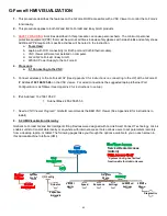
Страница 7: ...tions shown above Any modification to the installation orientation of the G Force without the written consent of Gorbel Inc Engineering will immediately void the warranty WARNING As a normal safety pr...

Страница 8: ...ither a Gorbel load hook or tooling supplied by others Tooling must meet the guidelines set forth by Gorbel Inc see Tooling Integration Guidelines on page 3 Improper tooling integration will result in...

Страница 9: ...heels pre assembled to the actuator trolley diagram 3A When a Gorbel G Force is to be used on a non Gorbel bridge system a universal adapter trolley is required diagram 3B Note The customer must provi...

Страница 10: ...connector into the actuator connector diagram 4C 4 5 Assure that the coils of the coil cord are centered around the wire rope when properly installed 4 6 Use the 16mm shoulder bolt and M12 jam nut to...

Страница 11: ...wire rope when properly installed 5A 8 Optional Install the hook or tooling using the retaining nut and lock washer The included flat washer is unnecessary in this application Use the open pilot hole...

Страница 12: ...Flatwasher Remote Mount Slide 5B 9 Assemble the remote mounted slide handle inside the remote mount bracket using the hardware provided diagram 5B3 Note This step is best completed on a workbench prio...

Страница 13: ...am 5C3 5C 9 Reinsert the clevis and cotter pin capturing the wire rope thimble in the swivel assembly diagram 5C3 5C 10 Continue to Step 6 on page 21 Note On suspended pendant equipped systems the wir...

Страница 14: ...l Cord Footer M8 Jam Nut G360 Swivel STRAIN RELIEF CLAMP MUST BE USED TO PREVENT DAMAGE TO G360 5D 9 Attach the pendant handle bracket directly to the tooling Assure that the mounting arrangement does...

Страница 15: ...e plate to the underside of the actuator using the supplied cap screws lockwashers and spacers as shown and ensure hardware is now completely tightened If an air hose is being installed leave hardware...

Страница 16: ...LLEY 83261 BEARING 65086 SNAP RING 2X 83259 2X 2001 12 83258 5F 3 Attach the plate to the underside of the actuator using the supplied cap screws lockwashers and spacers as shown and ensure hardware i...

Страница 17: ...shers holding the reinforcement plate to the underside of the actuator leaving the spacers in place and insert them through the air hose bracket and reattach to the underside of the actuator Tighten a...

Страница 18: ...e To avoid damaging the handle do not apply more than 200 lbs 90 kg to the grip or handlebars Note Remote handles must be mounted rigidly in order to function correctly For slide handles the mounting...

Страница 19: ...nsing Handle and one traditional handle is a supported configuration Note Handlebars and attachments for Remote Force Sensing Hub Handles must not exceed 25 lb 11 3 kg For optimal performance handleba...

Страница 20: ...TOP ENGAGED button located on the face of the handle 7 3 During the system power up the OLED at the handle will display G FORCE INITIALIZING If you are using a Force Sensing Handle after power is appl...

Страница 21: ...t Mode reaches 90 of the maximum fully loaded lifting speed and shuts the unit down It safely limits the maximum speed of travel in Float Mode CAUTION Actuating the operator present switch while in Fl...

Страница 22: ...rise due to tooling changes wear etc 9 2 Please contact Gorbel After the Sales Service department 585 924 6262 if any of the following occur DO NOT ATTEMPT TO REPAIR UNIT YOURSELF Excessive noise Unex...

Страница 23: ...OUNTING INSTRUCTIONS OPTION DIMENSIONS Diagram 10A Expansion I O block dimensions millimeters Diagram 10B Screw fastener drilling template TIP Expansion I O block mounting instructions only apply to i...

Страница 24: ...al to the amount of force applied Forces in lateral directions are not detected Note There is no traditional OPS When the force applied to the handle exceeds a small threshold the unit activates Stand...

Страница 25: ...beyond the maximum capacity of the G Force The red LEDs will flash and LIFT OVERLOAD will be displayed on the OLED to indicate to the operator the unit is overloaded The lift may be moved down to allo...

Страница 26: ...rope while the handle can be remote mounted to the tooling Use the appropriate extension cable from the G360 swivel assembly to the remote mount handle The handle operates exactly the same as if it we...

Страница 27: ...y and safety program mode are available It allows a minimum safe operation on a unit with a damaged handle broken I O electronics or other damaged peripheral control components that would make it dang...

Страница 28: ...enus V LIMITS MENU Virtual Limits menu SPEED MENU Lift Speed adjustment RESPONSE MENU Lift Response acceleration adjustment SETTINGS MENU Programmable Features on both the Q2 and iQ2 units ADVANCED SE...

Страница 29: ...press and release this button No Timeouts There is no Menu timeout when in Program Mode The menus will be active long enough to confirm any selections and can be exited sooner by activating the OPS se...

Страница 30: ...t the upper slowdown limit When traveling upward the load slows down from max speed once crossing this limit UPPER RESUME Keep the hook at the desired position and select to set the upper resume limit...

Страница 31: ...een enabling and disabling the load weight display Once enabled weight is displayed two seconds into standard operation unit idling ON_OFF DISPLAY Toggle the unit of the weight readout display between...

Страница 32: ...ed for a specific duration If this condition is met the G Force stops because of an anti recoil event The anti recoil Max Force detection mode can now be adjusted via the MAX FORCE setting below once...

Страница 33: ...for G Force 165 and Easy Arm 165 models or 101 of the rated capacity plus 5 lbs for all other models Minimum Limit 25 of the rated capacity Note a This can be monitored in Run Mode if WT READ ON is s...

Страница 34: ...TY TO LEVEL X Set Overload Detection Sensitivity to between 5 HIGH and 1 LOW one level decrements at a time By default the sensitivity is set at 5 1 5 RETURN BACK TO PREVIOUS MENU Return back to the S...

Страница 35: ...both the G Force logo button and the MENU button simultaneously for five seconds 2 The OLED will display UNLOCK CHECK while both buttons are being depressed 3 After five seconds PROGRAM UNLOCKED will...

Страница 36: ...LIMITS MENU Virtual Limits menu SPEED MENU Lift Speed adjustment RESPONSE MENU Lift Responsiveness Acceleration adjustment SERVICE MENU Customize and manage maintenance and service features WARNING I...

Страница 37: ...100 correspond to lowest and highest speed RETURN TO MAIN MENU Return back to the main selection menu Lift Responsiveness Acceleration Setting RESPONSE MENU RESPONSE LOW Set the lowest handle control...

Страница 38: ...Mode causing the unit to speed upward until hitting an object or a push force equivalent to the dropped weight Over Speed Detection Unit terminates Float Mode if speed exceeds maximum Float Mode spee...

Страница 39: ...y Arm 165 models or 101 of the rated capacity plus 5 lbs for all other models Minimum limit 25 of the rated capacity A warning is triggered if the tare weight is outside this range SET LIMIT LBS Set O...

Страница 40: ...ue to zero to un zero the load cell signal DEADBAND CENTER FSH deadband averaging to improve sensitivity of FSH signal by centering it DEFAULT SETTINGS Apply default setting of FSH Advanced Features A...

Страница 41: ...on and vice versa 6 Output External Control Output 2 This output option is controlled by the input on the optional expansion 8 point input output block set to EXTERNAL CONTROL INPUT 2 In this example...

Страница 42: ...iQ2 G Force stops at 10 25 lbs depending on unit capacity The Auto Home position programming is located at ADVANCED SETTINGS MENU 2 MENU SET HOME Move the G Force to the desired position in the verti...

Страница 43: ...wn Input Float Bias Up 1 2 Output External Control Output 1 Example user defined outputs Output External Control Output 2 Output Clamp Signal Output Run Mode Output Float Mode Output Fault Indicator T...

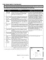
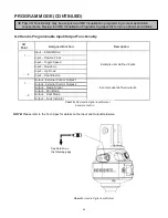
Страница 44: ...PROGRAM MODE CONTINUED 44...

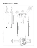
Страница 45: ...PROGRAM MODE CONTINUED lwER f R 1_ ll i A B L E A S S Y G o r b e l P N 7 8 6 6 6 O R Diagram J Handle IO Detail Slide Model 45...

Страница 46: ...PROGRAM MODE CONTINUED Diagram K Handle IO Detail Pendant Model 46...

Страница 47: ...any interference with foreign objects tooling work surfaces etc The actuator is extremely noisy Check the condition of the wire rope Check for any external damage to the actuator covers Float Mode doe...

Страница 48: ...ing condition has been resolved 3 ACOPOS Drive fault Drive detected condition that results in a shutdown A drive fault message will display on the OLED screen with the Drive Fault code The recovery fr...

Страница 49: ...ng Amber SRV WARN HRS Service Mode Amber SERVICE MODE Run Mode Overload Red WARNING LIFT OVERLOAD Overspeed No Light FLOAT MODE OVERSPEED Handle Idle Timeout Amber IDLE TIME EXCEEDED Handle Mode Green...

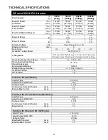
Страница 50: ...5A Lifting Media 3 16 dia 19x7 Preformed Stainless Steel Wire Rope 1 4 dia 19x7 Preformed Stainless Steel Wire Rope Operating Temperature Range F C 41 122 5 50 Operating Humidity Range Non Condensing...

Страница 51: ...s and should be more frequent as the rope approaches the end of its useful life A designated person shall perform periodic inspections This inspection shall cover the entire length of rope The individ...

Страница 52: ...nominal diameter greater than 1 64 4 mm for 1 4 6 35 mm diameter rope or 3 16 4 76 mm diameter rope 3 Broken wire removal criteria apply to wire rope operating on steel sheaves and drums However resul...

Страница 53: ...ard 4 Unspool rope from drum using jog down button while keeping tension on wire rope with other gloved hand Continue until lower limit is engaged 5 Insert a medium sized screwdriver between the white...

Страница 54: ...and pin and set aside 11 Using a 3mm hex wrench completely remove the four button head screws on front cover 12 Remove front cover from actuator and set aside upward to use as a bowl to hold future pa...

Страница 55: ...the unthreaded gate out towards you Place gate and hardware in front cover diagram R 23 Using a n M6mm hex wrench remove the two M8 socket head cap screws from the blue colored rope retainer and slid...

Страница 56: ...the previously removed hardware Torque hardware to compress lockwashers 6 For 330 lb 150kg and 660 lb 300kg units only Install slide the reinforcement bracket studs into channels and tighten the two 1...

Страница 57: ...r air hose if applicable removing coil cord mounting plate and removing pulley pin 2 Remove fasteners holding the reinforcement plate to the bottom of the actuator and nuts holding the U bolt freeing...

Страница 58: ...ation of hoist while traveling down is encountered the end effector or tooling on wire rope is not heavy enough to overcome the spring tension Loosen the outside nut one half turn and test the hoist o...

Страница 59: ...eight Under Hook and Span if applicable to your unit Level One Kit contains One Wire Rope Assembly One Coil Cord Assembly Level Two Kit contains One Wire Rope Assembly One Coil Cord Assembly One Hardw...

Страница 60: ...LY Tools depend on Handle type contact Gorbel After the Sales Service for more info disassembling the Handle 4 Procedure 5 1 Setting up Handle Configurations Disconnect BOTH handles from the Actuator...

Страница 61: ...ctioning of a multi handle G Force Easy Arm Run Mode Only one handle can be used to control motion of the G Force in Run Mode When one handle is being used OPS Triggered the other handle will not be o...

Страница 62: ...s on connecting to the AP at the G Force IP Address 192 168 105 26 on the VNC viewer For wired connections the suggested laptop Ethernet Port Configuration is as follows See Appendix F for instruction...

Страница 63: ...r Lower limit Upper Lower Slowdown Upper Resume and Slowdown Speed Speed Set Max Actuator Speed Up Down Toggle and Jog speed Response Set Handle Response levels Settings Weight Display Idle Time out F...

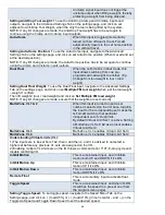
Страница 64: ...s the user to select the language of the HMI Currently only English is available IP Address This read only field will show the IP Address of the Actuator Reset Password Optionally update the password...

Страница 65: ...ved on the Actuator New IP Addr Enter the new IP address of the G Force E g Factory IP Address 192 168 105 26 Click Confirm to assign the IP address NOTE After clicking confirm the VNC will disconnect...

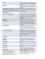
Страница 66: ...port to Selected Delete Selected To delete any xml file except factory as it cannot be deleted scroll using the arrow buttons to choose the xml file then press on Delete Selected USB USER This toggles...

Страница 67: ...ht has to be set on the Advanced Settings tab on the Settings Page AD Unclamp This input is typically wired to an unclamp request pushbutton When the input is on an Output Unclamp Signal turns on only...

Страница 68: ...en lift weight 2 tool load weight and click on Set Multiple FM load weight NOTE If any I O changes are made ensure that the weights are set correctly Multi Zone VL 1 2 When this input is turned on and...

Страница 69: ...s typically wired to actuate the clamping mechanism of an end effector tooling It turns on when AD UnClamp input is on and remains latched on when the input is released Clamp Unclamp Signal This outpu...

Страница 70: ...Menu Tab on the Settings page Click on the drop down to choose between Disabled or a specific Duration E g When the G Force has been used for the specified 500 hrs it will enable this output IO Confi...

Страница 71: ...and output features will be identical to Actuator I O iQ2 units will have Actuator I O and or an I O Block Handle I O The Handle I O will come with 2 inputs and 2 outputs Identical features to Actuat...

Страница 72: ...low down reduction point load must be at position where slow down begins when raising load Lower Slowdown Program the lower slow down reduction point load must be at position where slow down begins wh...

Страница 73: ...nward with the custom jog speed selected Actuator Speed Set Speed Changing the max set speed of the actuator Input Displays the location of where the Toggle Speed was configured either on the Actuator...

Страница 74: ...ins Only for 660 Lbs Med Default Float Mode gains with normal responsiveness stability Only for 660 Lbs High Highest more responsive least stable Float Mode gains Only for 660 Lbs Force Sensing Handle...

Страница 75: ...loat or custom Min Sec Select the mins or secs to configure the idle time Default Apply default excessive pause timer settings slide and pendant handles 45 seconds Float Mode 60 seconds and custom mot...

Страница 76: ...distance from the upper limit Anti Recoil Force On Off Over Force Detection Unit terminates Float Mode if user s operating force exceeds the maximum force limit or a dropped weight is detected by eva...

Страница 77: ...the desired value shown in the Value column NOTE Works when Dual Float Input is enabled Anti Drop Tool Weight Program the feature by clicking Set at the desired value shown in the Value column NOTE Wo...

Страница 78: ...led Overload This increments when the unit overloads Overspeed This increments when the unit kicks out of float mode based on Over speed Anti recoil settings Virtual Limit Exceeded If a Virtual Limit...

Страница 79: ...al in counts Hoist Lights indicate if the Upper Lower limit or Slack switches are triggered I O Toggle to choose between Actuator Handle Expansion Block I O and view the indication based on whether th...

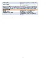
Страница 80: ...ecent 20 Drive Faults Refresh Log Updates the log list with any new or active errors 6 References Refer to Appendices Appendix B AP VNC Viewer Install Instructions Appendix C AP Connection QuickStart...

Страница 81: ...nnected to the G Force Access Point Field Customizations Instructions Access Point Settings The following parameters can be changed in the AP SSID Access Point Name Access Point Password Reset a Passw...

Страница 82: ...ear Figure 3 User Reset Page Click on Confirm Reset Ref Fig 3 A message Resetting Device The login screen will automatically reload when finished will appear and wait for the Login page will reappear...

Страница 83: ...This may require a shorter distance between the PC and the G Force to connect Additionally choose a transmit channel further away from the others E g When using 3 G Forces use 3 channels i e use 1 6 a...

Страница 84: ...iewer is the B R VNC Viewer Supported by Gorbel or use the VNC Viewer of your choice Click Here to automatically begin the download Or you can download the latest version here https www br automation...

Страница 85: ...Figure 9 VNC Viewer App 85...

Страница 86: ...nnected to the G Force 8 AP Connection QuickStart Guide 1 A Wirelessly connect to the G Force SSID Select the Internet Network icon in the taskbar and search for the WiFi Network with the G Force Acce...

Страница 87: ...y Default IP Address 192 168 105 26 NOTE The IP Addresses of the G Forces can be added as favorites with custom names to make it easier when working in an environment with multiple G Forces 4 Log in t...

Страница 88: ...nal protective equipment PPE that must be worn at all times include safety glasses with side shields and safety shoes Additional PPE required for specific activities will be noted in the instruction T...

Страница 89: ...click on Internet Protocol Version 4 TCP IPv4 to open General IP settings Ref Fig 3 Figure 12 Internet Protocol Settings Apply the following settings and then click OK and OK again to apply it to the...

Страница 90: ...DISTRIBUTOR NOT AN AGENT Gorbel and Purchaser agree that Purchaser has been put on notice that dealer or distributor is not Gorbel s agent in any respect for any reason Gorbel and Purchaser also agre...

Страница 91: ...requency Field Immunity EN 61000 4 4 Electrical Fast Transient Burst Surge EN 61000 4 5 Surge Immunity EN 61000 4 6 Conducted Susceptibility EN 61000 4 8 Power Frequency Immunity Low Voltage Directive...

Страница 92: ...tle puff of compressed air or a soft cloth to clean the sensor Do not apply any pressure to the lens or do anything that may scratch it Verify proper handle swivel functionality Pendant Handle Only Ch...

Отзывы: