Overload:
The servo controller will prevent the lift from moving upward if loaded beyond the maximum capacity of the
G-Force® BX ILD. When an overload condition is sensed, the Overload indicator is illuminated and the lift is
prevented from moving upward. The lift may be moved down to allow for the safe removal of the load. Releasing and
reactivating the operator present switch resets the overload condition.
Limit Switches:
The G-Force® is equipped with both mechanical Upper and Lower Limit switches, located in the
Actuator assembly. When the Upper Limit switch is triggered, the upward motion of the lift stops quickly at a controlled
deceleration rate. The controlled deceleration rate guarantees the load cannot come off the hook. When the Upper
Limit is triggered, the lift will move down but not up. The lower limit is set so that a minimum of two (2) full wraps of
wire rope remain on the drum pulley at all times. When the Lower Limit switch is triggered, the downward motion of
the lift stops quickly at a controlled deceleration rate. When the Lower Limit is triggered, the lift will only move up and
not down.
Slack Switch:
The G-Force® is equipped with a pair of Slack Switches that sense tension in the wire rope and trips
when the wire rope develops slack. The switches are located inside the Actuator assembly. When the Slack Switches
sense slack in the wire rope, downward movement of the lift is stopped to minimize the amount of wire rope unwound
from the drum pulley. When slack in the wire rope is sensed, the lift will only move up but not down.
Remote Mount Handle (System Option):
The lifting device is capable of operating with the handle displaced from
the wire rope (not in-line with the wire rope). For example, if an end user has tooling that is too large for the operator
to safely reach and operate the handle in the standard position, remote mounting the handle is recommended. The
tooling must be mounted (and balanced) on the end of the wire rope, while the handle can be remote mounted. The
tooling
must
be attached to the end of the wire rope with a swivel assembly (supplied by Gorbel, Inc.). Failure to mount
the tooling with a swivel assembly can result in premature failure of both the wire rope and the coil cord. The remote
mounted handle is linked to the coil cord via extension cables and connectors. The handle operates exactly the same
as if it were mounted in-line. If the device is equipped for Float Mode, a load cell assembly is provided that must also
be mounted between the tooling and the end of the wire rope. The handle is linked to the load cell via an extension
cable and connectors. **The end user must supply Gorbel, Inc., with the required length of the extension cables such
that they can be safely routed and clamped to the tooling. Always include the distance for bends and turns when
providing the extension length.
CONTROLS INTERFACE FEATURES
1.
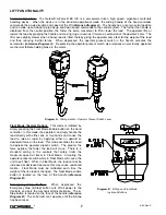
Jog Switch Push Buttons:
The Jog Switch Buttons allow qualified personnel to replace the wire rope (load
cable) on the system. To effectively operate the Jog Switch Buttons, all electrical cables must be connected and
power on. Depressing the “Up” jog switch button will enable the motor and cause the system to reel the wire
rope into the actuator and onto the main pulley. Depressing the “Down” jog switch button will enable the motor
and cause the system to pay out the wire rope from the actuator and off of the main pulley. The handle and
operator present switch are not to be operated during use of the Jog Switch Buttons.
Diagram C.
Controls Interface Display.
WARNING
The Jog Switch buttons are for system maintenance and load testing use only, and should not be
manipulated during normal operation of the G-Force® BX ILD. Operation of the Jog Switch buttons dur-
ing normal operation increases the risk of personal injury to the operator.
8
4/04-Rev. S
®
Содержание 150 BX G-Force
Страница 26: ...Figure A3 bottom Figure A4 top 150 BX Actuator Assembly 25 4 04 Rev S ...
Страница 27: ...Figure A5 150 BX Actuator Assembly 26 4 04 Rev S ...
Страница 28: ...Figure A6 150 BX Actuator Assembly 27 4 04 Rev S ...
Страница 29: ...Figure A7 bottom Figure A8 top 150 BX Actuator Assembly 28 4 04 Rev S ...
Страница 30: ...Figure A9 bottom Figure A10 top 150 BX Actuator Assembly 29 4 04 Rev S ...
Страница 31: ...Figure A11 bottom Figure A12 top 150 BX Actuator Assembly 30 4 04 Rev S ...
Страница 32: ...Figure A13 150 BX Actuator Assembly 31 4 04 Rev S ...
Страница 33: ...Figure A14 150 BX Actuator Assembly 32 4 04 Rev S ...
Страница 35: ...Figure B3 bottom Figure B4 top 300 380 BX Actuator Assembly 34 4 04 Rev S ...
Страница 36: ...Figure B5 300 380 BX Actuator Assembly 35 4 04 Rev S ...
Страница 37: ...Figure B6 300 380 BX Actuator Assembly 36 4 04 Rev S ...
Страница 38: ...Figure B7 bottom Figure B8 top 300 380 BX Actuator Assembly 37 4 04 Rev S ...
Страница 39: ...Figure B9 bottom Figure B10 top 300 380 BX Actuator Assembly 38 4 04 Rev S ...
Страница 40: ...Figure B11 bottom Figure B12 top 300 380 BX Actuator Assembly 39 4 04 Rev S ...
Страница 41: ...40 Figure B13 300 380 BX Actuator Assembly 4 04 Rev S ...
Страница 42: ...Figure B14 300 380 BX Actuator Assembly 41 4 04 Rev S ...
Страница 44: ...Figure C3 Standard Handle Assembly 43 4 04 Rev S ...
Страница 45: ...Figure C4 Standard Handle Assembly 44 4 04 Rev S ...
Страница 46: ...Figure C5 bottom Figure C6 top Standard Handle Assembly 45 4 04 Rev S ...
Страница 47: ...Figure C7 bottom Figure C8 top Standard Handle Assembly 46 4 04 Rev S ...
Страница 48: ...Figure C9 bottom Figure C10 top Standard Handle Assembly 47 4 04 Rev S ...
Страница 49: ...Figure C11 bottom Figure C12 top Standard Handle Assembly 48 4 04 Rev S ...
Страница 50: ...Figure C13 Standard Handle Assembly 49 4 04 Rev S ...
Страница 52: ...Figure D3 bottom Figure D4 top Float Mode Handle Assembly 51 4 04 Rev S ...
Страница 53: ...Figure D5 bottom Figure D6 top Float Mode Handle Assembly 52 4 04 Rev S ...
Страница 54: ...Figure D7 bottom Figure D8 top Float Mode Handle Assembly 53 4 04 Rev S ...
Страница 55: ...Figure D9 bottom Figure D10 top Float Mode Handle Assembly 54 4 04 Rev S ...
Страница 56: ...Figure D11 Float Mode Handle Assembly 55 4 04 Rev S ...
Страница 58: ...Figure E2 Air Coil Cord Assembly Standard Float Mode 57 4 04 Rev S ...
Страница 59: ...Figure E3 Remote Mount Coil Cord Standard Float Mode 58 4 04 Rev S ...
Страница 60: ...Figure E4 Air Remote Mount Coil Cord Standard Float Mode 59 4 04 Rev S ...
Страница 61: ...APPENDIX F CONTROLS SCHEMATIC DRAWINGS Figure F1 Remote Load Cell Assembly 60 4 04 Rev S ...
Страница 62: ...Figure F2 BX Controls Schematic 61 4 04 Rev S ...
Страница 63: ...APPENDIX G OVERALL G FORCE REFERENCE DIMENSIONS Figure G1 BX G Force 150 Overall Dimensions 62 4 04 Rev S ...
Страница 64: ...Figure G2 BX G Force 300 380 Overall Dimensions 63 4 04 Rev S ...
Страница 65: ...APPENDIX H BX G FORCE HANDLE REFERENCE DIMENSIONS Figure H1 BX G Force Handle Detail Dimensions 64 4 04 Rev S ...
Страница 66: ...APPENDIX I COMPONENT LAYOUT DRAWINGS Figure I1 150 Standard Inline Component Layout 65 4 04 Rev S ...
Страница 67: ...Figure I2 300 380 Standard Inline Component Layout 66 4 04 Rev S ...
Страница 68: ...Figure I3 Standard Remote Mount Component Layout 67 4 04 Rev S ...


