5.4
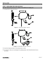
After verifying the Disconnect Switch is turned
OFF
, connect the newly installed receptacle to the Male Plug at
the G-Force® BX ILD.
STEP 6 - AIR CONNECTION (OPTION)
6.1
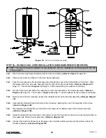
Assemble one of the Female fittings (provided) to the end of the input air hose (not provided).
6.2
Assemble the other Female fitting (provided) to the end of the tooling airline (not provided).
6.3
Connect both fittings to the respective ends of the Nycoil air hose in the Coil Cord.
6.4
Release the valve supplying air to the G-Force® BX ILD. Inspect and assure that all connections are properly
made and there are no air leaks.
STEP 7 - INITIAL POWER-UP
7.1
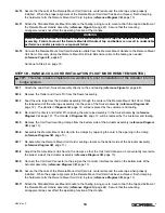
Turn on the Disconnect Switch (by others) to apply power to the G-Force® BX ILD.
7.2
Disengage the Emergency Stop (E-stop) button located on the front face of the handle.
7.3
The system will complete the “Power Up Diagnostic Test” described in the “Controls Interface Features” section
of this manual on pages 6 & 7.
7.4
When the “Power Up Diagnostic Test” has been successfully completed, the unit is ready for operation.
7.5
Standard Operation: Depress the operator present switch on the Handle and run the unit up and down several
times (at least 20 times in each direction) to assure that there is no mechanical binding in the lift system or
electrical connection issues.
7.6
Float Mode (if equipped): Lift up a load greater than 20 lbs. Settle the Load and depress the “Float Mode
Enabled” button. ***Do not hold onto the part while initiating Float Mode.*** This will give the unit a false
reading and cause excessive drift. Grasping the load, run the unit up and down several times (at least 20 times
in each direction) to assure proper operation. Float Mode should provide a nice smooth feel.
7.7
Finally, test the operation of any special tooling that may have been integrated to the G-Force® BX ILD.
STEP 8 - ADJUSTING LIFT SPEED
8.1
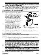
Take note of the speed of the unit as it is raised and lowered during Step 7. The speed of the G-Force® BX ILD
can be adjusted using the 10 position Speed Selector switch located at the Controls Interface back at the bottom
face of the Actuator assembly.
TIP:
G-Force® BX ILD units (Standard Inline or Remote Mounted) that are ordered with Air
power, have a 3/8” ID Nycoil air hose integrated into the full length of the Coil Cord. The Coil
Cord is provided with two (2) Male fittings located at both ends of the air hose. Gorbel also
provides both mating Female fittings for 3/8” ID air hose.
TIP:
Do not depress the operator present switch on the Handle during start-up. Depressing
the Handle during the start-up process will result in a drive fault.
TIP:
The operator should always keep the operator present switch depressed while
operating the unit in Standard Mode. Frequent pressing and releasing of the operator
present switch (which is common for first time users) will result in jerky movement, and is not
recommended.
WARNING
Gorbel, Inc., does not provide integrated tooling for the G-Force® BX ILD. All tooling related questions should
be directed to the tooling manufacturer or supplier.
16
4/04-Rev. S
®
Содержание 150 BX G-Force
Страница 26: ...Figure A3 bottom Figure A4 top 150 BX Actuator Assembly 25 4 04 Rev S ...
Страница 27: ...Figure A5 150 BX Actuator Assembly 26 4 04 Rev S ...
Страница 28: ...Figure A6 150 BX Actuator Assembly 27 4 04 Rev S ...
Страница 29: ...Figure A7 bottom Figure A8 top 150 BX Actuator Assembly 28 4 04 Rev S ...
Страница 30: ...Figure A9 bottom Figure A10 top 150 BX Actuator Assembly 29 4 04 Rev S ...
Страница 31: ...Figure A11 bottom Figure A12 top 150 BX Actuator Assembly 30 4 04 Rev S ...
Страница 32: ...Figure A13 150 BX Actuator Assembly 31 4 04 Rev S ...
Страница 33: ...Figure A14 150 BX Actuator Assembly 32 4 04 Rev S ...
Страница 35: ...Figure B3 bottom Figure B4 top 300 380 BX Actuator Assembly 34 4 04 Rev S ...
Страница 36: ...Figure B5 300 380 BX Actuator Assembly 35 4 04 Rev S ...
Страница 37: ...Figure B6 300 380 BX Actuator Assembly 36 4 04 Rev S ...
Страница 38: ...Figure B7 bottom Figure B8 top 300 380 BX Actuator Assembly 37 4 04 Rev S ...
Страница 39: ...Figure B9 bottom Figure B10 top 300 380 BX Actuator Assembly 38 4 04 Rev S ...
Страница 40: ...Figure B11 bottom Figure B12 top 300 380 BX Actuator Assembly 39 4 04 Rev S ...
Страница 41: ...40 Figure B13 300 380 BX Actuator Assembly 4 04 Rev S ...
Страница 42: ...Figure B14 300 380 BX Actuator Assembly 41 4 04 Rev S ...
Страница 44: ...Figure C3 Standard Handle Assembly 43 4 04 Rev S ...
Страница 45: ...Figure C4 Standard Handle Assembly 44 4 04 Rev S ...
Страница 46: ...Figure C5 bottom Figure C6 top Standard Handle Assembly 45 4 04 Rev S ...
Страница 47: ...Figure C7 bottom Figure C8 top Standard Handle Assembly 46 4 04 Rev S ...
Страница 48: ...Figure C9 bottom Figure C10 top Standard Handle Assembly 47 4 04 Rev S ...
Страница 49: ...Figure C11 bottom Figure C12 top Standard Handle Assembly 48 4 04 Rev S ...
Страница 50: ...Figure C13 Standard Handle Assembly 49 4 04 Rev S ...
Страница 52: ...Figure D3 bottom Figure D4 top Float Mode Handle Assembly 51 4 04 Rev S ...
Страница 53: ...Figure D5 bottom Figure D6 top Float Mode Handle Assembly 52 4 04 Rev S ...
Страница 54: ...Figure D7 bottom Figure D8 top Float Mode Handle Assembly 53 4 04 Rev S ...
Страница 55: ...Figure D9 bottom Figure D10 top Float Mode Handle Assembly 54 4 04 Rev S ...
Страница 56: ...Figure D11 Float Mode Handle Assembly 55 4 04 Rev S ...
Страница 58: ...Figure E2 Air Coil Cord Assembly Standard Float Mode 57 4 04 Rev S ...
Страница 59: ...Figure E3 Remote Mount Coil Cord Standard Float Mode 58 4 04 Rev S ...
Страница 60: ...Figure E4 Air Remote Mount Coil Cord Standard Float Mode 59 4 04 Rev S ...
Страница 61: ...APPENDIX F CONTROLS SCHEMATIC DRAWINGS Figure F1 Remote Load Cell Assembly 60 4 04 Rev S ...
Страница 62: ...Figure F2 BX Controls Schematic 61 4 04 Rev S ...
Страница 63: ...APPENDIX G OVERALL G FORCE REFERENCE DIMENSIONS Figure G1 BX G Force 150 Overall Dimensions 62 4 04 Rev S ...
Страница 64: ...Figure G2 BX G Force 300 380 Overall Dimensions 63 4 04 Rev S ...
Страница 65: ...APPENDIX H BX G FORCE HANDLE REFERENCE DIMENSIONS Figure H1 BX G Force Handle Detail Dimensions 64 4 04 Rev S ...
Страница 66: ...APPENDIX I COMPONENT LAYOUT DRAWINGS Figure I1 150 Standard Inline Component Layout 65 4 04 Rev S ...
Страница 67: ...Figure I2 300 380 Standard Inline Component Layout 66 4 04 Rev S ...
Страница 68: ...Figure I3 Standard Remote Mount Component Layout 67 4 04 Rev S ...


