


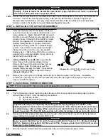


3A.10
Assure that the coils of the Remote Mount Coil Cord are centered around the wire rope when properly
installed. When the proper alignment of the Remote Mount Coil Cord has been achieved, finish clamping
the hardware to fix the Remote Mount Coil Cord in place (
reference Diagram 3B
, page 13).
3A.11
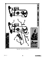
Attach the Standard Remote Mount Handle to the Tooling, being sure to mount at both the top and bottom of
the Remote Mount Handle assembly (
reference Figure I3
, page 67). Assure that the mounting
arrangement does not effect the operating function of the Handle.
3A.12
Connect the Remote Mount Coil Cord Extension cable from the Remote Mount Handle to the Remote Mount
Coil Cord. Securely clamp the Remote Mount Coil Cord Extension cable to the tooling as needed
(
reference Figure I3
, page 67).
Continue to Step 4 on page 15.
STEP 3B - HANDLE-COIL CORD INSTALLATION (FLOAT MODE REMOTE MOUNTED)
3B.1
Attach the Load Cell - Swivel assembly directly to the end tooling (
reference Figure I4
, page 68).
3B.2
Remove the Cotter and Clevis Pin from the Swivel assembly.
3B.3
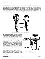
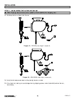
Feed the wire rope from the Actuator assembly through the center of the Remote Mount Coil Cord. Slide
the looped end of the wire rope assembly into the yoke of the Swivel assembly (
reference Diagram 3A
,
page 12). The Handle in
Diagram 3A
, page 12, will be replaced by the customer end tooling.
3B.4
Re-insert the Clevis and Cotter Pin capturing the wire rope assembly in the Swivel assembly (
reference
Diagram 3A
, page 12). The Handle in
Diagram 3A
, page 12, will be replaced by the customer end tooling.
3B.5
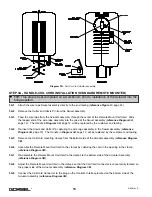
Remove the Coil Cord mounting clamps from the bottom side of the Actuator assembly (
reference Diagram
3B
, page 13).
3B.6
Assemble the Remote Mount Coil Cord to the clamps by capturing the cord in the opening in the clamp
(
reference Diagram 3B
, page 13).
3B.7
Re-assemble the Remote Mount Coil Cord mounting clamps to the bottom side of the Actuator assembly
(
reference Diagram 3B
, page 13).
3B.8
Adjust the Remote Mount Coil Cord in the clamps so that the Coil Cord Connector is conveniently located on
the proper side of the Actuator assembly (
reference Diagram 3B
, page 13).
3B.9
Connect the Coil Cord Connector to the plug on the Control’s Interface located on the bottom side of the
Actuator assembly (
reference Diagram 3B
, page 13).
3B.10
Assure that the coils of the Remote Mount Coil Cord are centered around the wire rope when properly
installed. When the proper alignment of the Remote Mount Coil Cord has been achieved, finish clamping
the hardware to fix the Remote Mount Coil Cord in place (
reference Diagram 3B
, page 13).
3B.11
Attach the Standard Remote Mount Handle to the Tooling, being sure to mount at both the top and bottom of
the Remote Mount Handle assembly (
reference Figure I4
, page 68). Assure that the mounting
arrangement does not affect the operating function of the Handle.
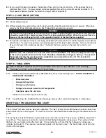
WARNING
Remote Mount G-Force® BX Handles must be mounted at both the top and bottom of the Handle
assembly. Failure to mount the Remote Mounted Handle at top and bottom can result in undesirable
performance and/or premature component failure.
TIP:
This step is best completed on a workbench, prior to installation of the Actuator into the
bridge system.
14
4/04-Rev. S
®
Содержание 150 BX G-Force
Страница 26: ...Figure A3 bottom Figure A4 top 150 BX Actuator Assembly 25 4 04 Rev S ...
Страница 27: ...Figure A5 150 BX Actuator Assembly 26 4 04 Rev S ...
Страница 28: ...Figure A6 150 BX Actuator Assembly 27 4 04 Rev S ...
Страница 29: ...Figure A7 bottom Figure A8 top 150 BX Actuator Assembly 28 4 04 Rev S ...
Страница 30: ...Figure A9 bottom Figure A10 top 150 BX Actuator Assembly 29 4 04 Rev S ...
Страница 31: ...Figure A11 bottom Figure A12 top 150 BX Actuator Assembly 30 4 04 Rev S ...
Страница 32: ...Figure A13 150 BX Actuator Assembly 31 4 04 Rev S ...
Страница 33: ...Figure A14 150 BX Actuator Assembly 32 4 04 Rev S ...
Страница 35: ...Figure B3 bottom Figure B4 top 300 380 BX Actuator Assembly 34 4 04 Rev S ...
Страница 36: ...Figure B5 300 380 BX Actuator Assembly 35 4 04 Rev S ...
Страница 37: ...Figure B6 300 380 BX Actuator Assembly 36 4 04 Rev S ...
Страница 38: ...Figure B7 bottom Figure B8 top 300 380 BX Actuator Assembly 37 4 04 Rev S ...
Страница 39: ...Figure B9 bottom Figure B10 top 300 380 BX Actuator Assembly 38 4 04 Rev S ...
Страница 40: ...Figure B11 bottom Figure B12 top 300 380 BX Actuator Assembly 39 4 04 Rev S ...
Страница 41: ...40 Figure B13 300 380 BX Actuator Assembly 4 04 Rev S ...
Страница 42: ...Figure B14 300 380 BX Actuator Assembly 41 4 04 Rev S ...
Страница 44: ...Figure C3 Standard Handle Assembly 43 4 04 Rev S ...
Страница 45: ...Figure C4 Standard Handle Assembly 44 4 04 Rev S ...
Страница 46: ...Figure C5 bottom Figure C6 top Standard Handle Assembly 45 4 04 Rev S ...
Страница 47: ...Figure C7 bottom Figure C8 top Standard Handle Assembly 46 4 04 Rev S ...
Страница 48: ...Figure C9 bottom Figure C10 top Standard Handle Assembly 47 4 04 Rev S ...
Страница 49: ...Figure C11 bottom Figure C12 top Standard Handle Assembly 48 4 04 Rev S ...
Страница 50: ...Figure C13 Standard Handle Assembly 49 4 04 Rev S ...
Страница 52: ...Figure D3 bottom Figure D4 top Float Mode Handle Assembly 51 4 04 Rev S ...
Страница 53: ...Figure D5 bottom Figure D6 top Float Mode Handle Assembly 52 4 04 Rev S ...
Страница 54: ...Figure D7 bottom Figure D8 top Float Mode Handle Assembly 53 4 04 Rev S ...
Страница 55: ...Figure D9 bottom Figure D10 top Float Mode Handle Assembly 54 4 04 Rev S ...
Страница 56: ...Figure D11 Float Mode Handle Assembly 55 4 04 Rev S ...
Страница 58: ...Figure E2 Air Coil Cord Assembly Standard Float Mode 57 4 04 Rev S ...
Страница 59: ...Figure E3 Remote Mount Coil Cord Standard Float Mode 58 4 04 Rev S ...
Страница 60: ...Figure E4 Air Remote Mount Coil Cord Standard Float Mode 59 4 04 Rev S ...
Страница 61: ...APPENDIX F CONTROLS SCHEMATIC DRAWINGS Figure F1 Remote Load Cell Assembly 60 4 04 Rev S ...
Страница 62: ...Figure F2 BX Controls Schematic 61 4 04 Rev S ...
Страница 63: ...APPENDIX G OVERALL G FORCE REFERENCE DIMENSIONS Figure G1 BX G Force 150 Overall Dimensions 62 4 04 Rev S ...
Страница 64: ...Figure G2 BX G Force 300 380 Overall Dimensions 63 4 04 Rev S ...
Страница 65: ...APPENDIX H BX G FORCE HANDLE REFERENCE DIMENSIONS Figure H1 BX G Force Handle Detail Dimensions 64 4 04 Rev S ...
Страница 66: ...APPENDIX I COMPONENT LAYOUT DRAWINGS Figure I1 150 Standard Inline Component Layout 65 4 04 Rev S ...
Страница 67: ...Figure I2 300 380 Standard Inline Component Layout 66 4 04 Rev S ...
Страница 68: ...Figure I3 Standard Remote Mount Component Layout 67 4 04 Rev S ...