<
24
>
Numb
ering
Device description
Functional description
Bit number
1
MINI SAS HD High Speed
Connector
Used for transmission of 12G/b SAS or 6G/b
SATA signals.
J2,J3,J4
2
Power connector
Backplane power transfer connector for
transmission of 12V power.
J1
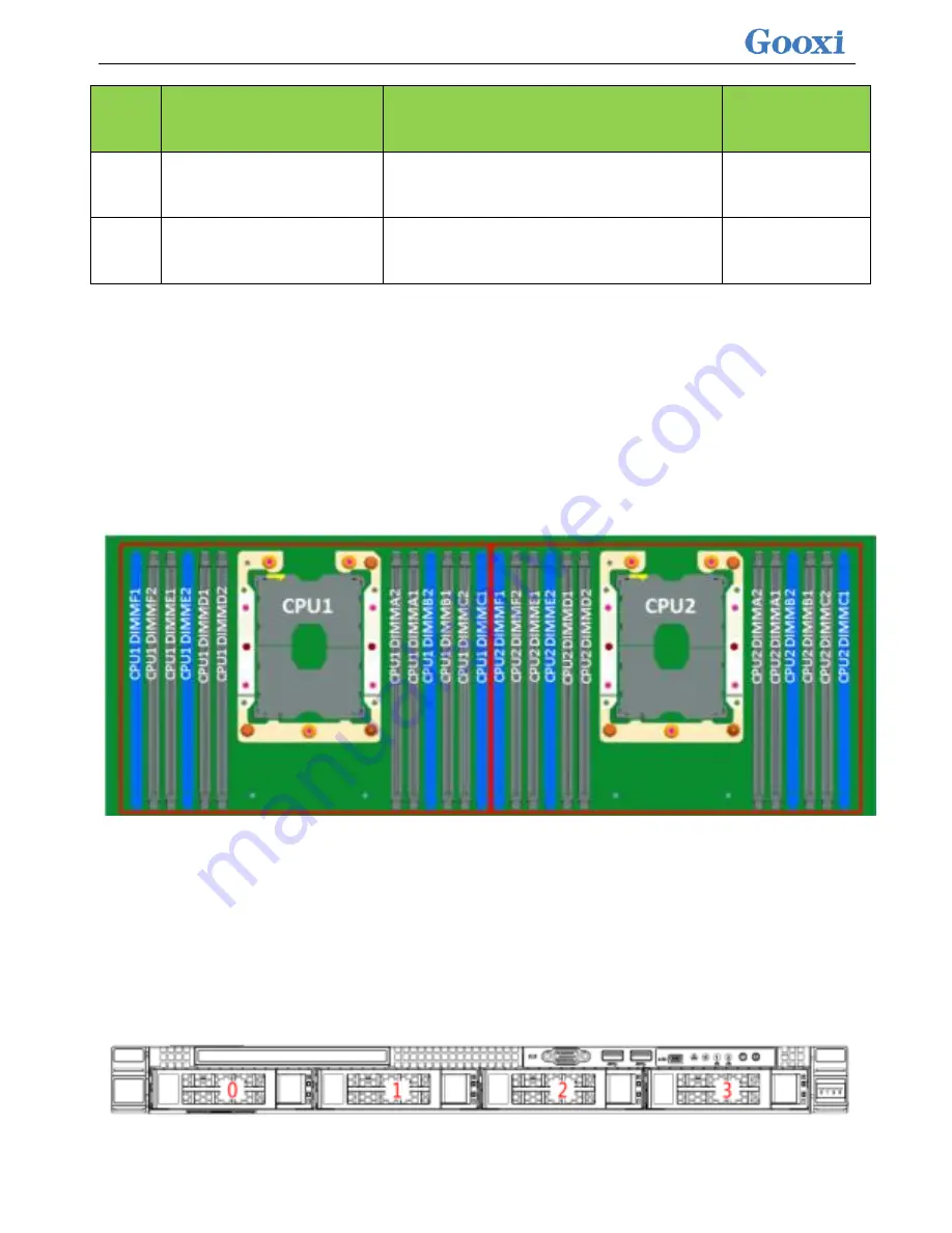
2.4.5 DIMM slot location
The motherboard uses Intel Purley platform with Intel Xeon SkyLake CPU,
supports 12 DDR4 channels, 24 DDR4 slots, supports DDR4 ECC
RDIMMs/LRDIMMs
server
memory,
memory
frequency
support
1866/2133/2400/2666MHz; location as shown below :
2.4.6 Hard disk label
1U4 bay 3.5 inch disk model
Содержание Purley Platform 1U
Страница 1: ...Purley Platform 1U L Shape Server Product Manual REV 1 0...
Страница 4: ...functions Chapter 7 RAID Setup Instructions...
Страница 8: ...Chapter 10 Product Specifications 283...
Страница 18: ...10 2 3 System model specifications 1U4 bay 3 5 inch disk model positive...
Страница 53: ...45...
Страница 58: ...50...
Страница 78: ...70...
Страница 79: ...71...
Страница 80: ...72 6 2 5ALL CPU Information Display the system CPU model version and other details...
Страница 86: ...78 Disabled Off Default Disabled 6 2 10 SIO Configuration...
Страница 109: ...101 6 2 24 Per Socket Configuration menu...
Страница 115: ...107 6 2 27 Memory Topology menu Displays the current system memory details...
Страница 141: ...133 Create a RAID a Select Create RAID Volume and press enter Picture 1 4 Figure 1 4 Creating a RAID...
Страница 143: ...135 c RAID Level Select the raid level of the group as shown in Figure 1 6 Figure 1 6 Selecting a RAID Level for a Group...
Страница 160: ...152 d Enter the RAID card configuration interface as shown in the following figure...
Страница 162: ...154 b Enter the screen shown below select Select RAID Level set the RAID level and press Enter...
Страница 163: ...155 c Select Selcect Physical Disks to enter the RAID page of the selected group RAID...
Страница 164: ...156 d Select the disk you want to use to configure the RAID Enabled is selected select Apply Changes and press Enter...
Страница 165: ...157 e Change Confirm to Enabled and select Yes to complete RAID configuration...
Страница 168: ...160 Delete RAID a Select Virtual Disk Management and press enter...
Страница 169: ...161 b Select Select Virtual Disk Operations and press enter...
Страница 170: ...162 c Select Delete Virtual Disk and press enter...
Страница 171: ...163 d Change Confirm to Enabled check Yes and press enter to finish deleting RAID...
Страница 179: ...171 d Go to the screen shown in Figure 3 5 Select Go and press Enter Figure 3 5 Select Go...
Страница 185: ...177 e Enter the interface as shown in Figure 3 11 Select Select Drives and press Enter Figure 3 11 Select Select Drives...
Страница 197: ...189 d Go to the screen shown in Figure 3 21 Choose Go and press Enter Figure 3 21 Select Go...
Страница 203: ...195 d Go to the screen shown in Figure 2 38 Choose Go and press Enter Figure 2 38 Select Go...
Страница 204: ...196 e Enter the interface as shown in Figure 2 39 Choose Confirm Enabled Yes and press Enter Figure 2 39 Confirm Delete...
Страница 205: ...197 f Enter the interface as shown in Figure 2 40 to delete the RAID operation Figure 2 40 Complete RAID Deletion...
Страница 209: ...201 d Go to the Figure 2 44 screen Choose Go and press Enter Figure 2 44 Select Go...
Страница 214: ...206 d Go to the screen shown in Figure 2 49 Choose Go and press Enter Figure 2 49 Select Go...
Страница 225: ...217 d Go to the Figure 2 60 screen Choose Go and press Enter Figure 2 60 Select Go...
Страница 232: ...224 e Go to the screen shown in Figure 2 67 Choose Go and press Enter Figure 2 67 Select Go...
Страница 239: ...231 e Go to the interface shown in Figure 2 74 Choose Go and press Enter Figure 2 74 Select Go...
Страница 245: ...237 d Go to the screen shown in Figure 2 80 Choose Go and press Enter Figure 2 80 Select Go...
Страница 249: ...241 h Go to the screen shown in Figure 2 84 Select Start Operation and press Enter Figure 2 84 Start Operation screen...
Страница 250: ...242 i Go to the screen shown in Figure 2 85 Choose OK and press Enter Figure 2 85 Select OK...
Страница 255: ...247 e Enter the screen shown in Figure 2 90 Select Confirm Enabled Yes and press Enter Figure 2 90 Confirm Clear...
Страница 289: ...281 Diagram3 5 KVM interface...
Страница 293: ...285 Figure 3 9 SOL operation interface...
Страница 295: ...287 T1DM E2 Card Connector Connector serial number description Note VGA VGA Connector VGA video output connector...
Страница 301: ...293...


