<
13
>
3. In addition, it can also support 1* non-standard PCIEX8 SAS/RAID card slot+1*
non-standard PCIEX8 card slot;
hard disk
Supports up to 10 3.5-inch SAS/SATA (HDD/SSD)
M.2 SSD
PCIE Gen3 X4 M.2 SSD(Support M.2 SSD length 80mm and 110mm)
LAN
Two onboard 1GE, two optional 1GE/4 1GE/2 10GE/4 10GE/2 40GE network
daughter cards
External port
Front port: VGA, 1 USB3.0, 1 Mini USB for LCD
Rear: VGA, 2 USB3.0, 1 management network port, 2 RJ45 network ports
management
Onboard iBMC management module supporting management features such as
IPMI, SOL, KVM Over IP, and virtual media
Optional LCD Management Module
System fan
N+1 hot swap redundant fan
power supply
Platinum-class 550W, 800W, 1300W, 1600W hot swappable redundant power
supply with optional support for -48V, 240V, and 338V DC
Dimensions
1Ucabinet type, standard guide rails, maximum depth: 788 mm, including 808 mm
lugs
2.4 System components introduction
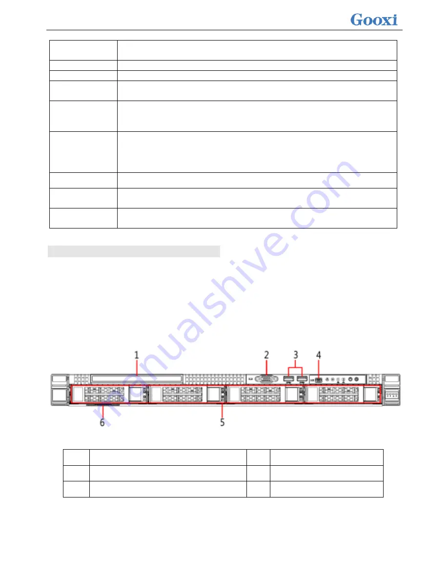
2.4.1 Front panel components
1U4 bay 3.5 inch disk model
1
Built-in DVD drive
4
LCD dedicated interface
2
VGA interface
5
hard disk
3
USB 3.0 interface
6
Tag card
1U10 disk position 2.5 inch disk model
Содержание Purley Platform 1U
Страница 1: ...Purley Platform 1U L Shape Server Product Manual REV 1 0...
Страница 4: ...functions Chapter 7 RAID Setup Instructions...
Страница 8: ...Chapter 10 Product Specifications 283...
Страница 18: ...10 2 3 System model specifications 1U4 bay 3 5 inch disk model positive...
Страница 53: ...45...
Страница 58: ...50...
Страница 78: ...70...
Страница 79: ...71...
Страница 80: ...72 6 2 5ALL CPU Information Display the system CPU model version and other details...
Страница 86: ...78 Disabled Off Default Disabled 6 2 10 SIO Configuration...
Страница 109: ...101 6 2 24 Per Socket Configuration menu...
Страница 115: ...107 6 2 27 Memory Topology menu Displays the current system memory details...
Страница 141: ...133 Create a RAID a Select Create RAID Volume and press enter Picture 1 4 Figure 1 4 Creating a RAID...
Страница 143: ...135 c RAID Level Select the raid level of the group as shown in Figure 1 6 Figure 1 6 Selecting a RAID Level for a Group...
Страница 160: ...152 d Enter the RAID card configuration interface as shown in the following figure...
Страница 162: ...154 b Enter the screen shown below select Select RAID Level set the RAID level and press Enter...
Страница 163: ...155 c Select Selcect Physical Disks to enter the RAID page of the selected group RAID...
Страница 164: ...156 d Select the disk you want to use to configure the RAID Enabled is selected select Apply Changes and press Enter...
Страница 165: ...157 e Change Confirm to Enabled and select Yes to complete RAID configuration...
Страница 168: ...160 Delete RAID a Select Virtual Disk Management and press enter...
Страница 169: ...161 b Select Select Virtual Disk Operations and press enter...
Страница 170: ...162 c Select Delete Virtual Disk and press enter...
Страница 171: ...163 d Change Confirm to Enabled check Yes and press enter to finish deleting RAID...
Страница 179: ...171 d Go to the screen shown in Figure 3 5 Select Go and press Enter Figure 3 5 Select Go...
Страница 185: ...177 e Enter the interface as shown in Figure 3 11 Select Select Drives and press Enter Figure 3 11 Select Select Drives...
Страница 197: ...189 d Go to the screen shown in Figure 3 21 Choose Go and press Enter Figure 3 21 Select Go...
Страница 203: ...195 d Go to the screen shown in Figure 2 38 Choose Go and press Enter Figure 2 38 Select Go...
Страница 204: ...196 e Enter the interface as shown in Figure 2 39 Choose Confirm Enabled Yes and press Enter Figure 2 39 Confirm Delete...
Страница 205: ...197 f Enter the interface as shown in Figure 2 40 to delete the RAID operation Figure 2 40 Complete RAID Deletion...
Страница 209: ...201 d Go to the Figure 2 44 screen Choose Go and press Enter Figure 2 44 Select Go...
Страница 214: ...206 d Go to the screen shown in Figure 2 49 Choose Go and press Enter Figure 2 49 Select Go...
Страница 225: ...217 d Go to the Figure 2 60 screen Choose Go and press Enter Figure 2 60 Select Go...
Страница 232: ...224 e Go to the screen shown in Figure 2 67 Choose Go and press Enter Figure 2 67 Select Go...
Страница 239: ...231 e Go to the interface shown in Figure 2 74 Choose Go and press Enter Figure 2 74 Select Go...
Страница 245: ...237 d Go to the screen shown in Figure 2 80 Choose Go and press Enter Figure 2 80 Select Go...
Страница 249: ...241 h Go to the screen shown in Figure 2 84 Select Start Operation and press Enter Figure 2 84 Start Operation screen...
Страница 250: ...242 i Go to the screen shown in Figure 2 85 Choose OK and press Enter Figure 2 85 Select OK...
Страница 255: ...247 e Enter the screen shown in Figure 2 90 Select Confirm Enabled Yes and press Enter Figure 2 90 Confirm Clear...
Страница 289: ...281 Diagram3 5 KVM interface...
Страница 293: ...285 Figure 3 9 SOL operation interface...
Страница 295: ...287 T1DM E2 Card Connector Connector serial number description Note VGA VGA Connector VGA video output connector...
Страница 301: ...293...


