background image

DISASSEMBLY INSTRUCTIONS

B2-3

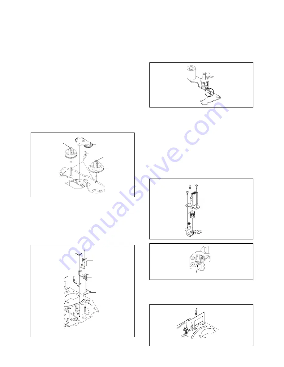
2-11: S REEL/T REEL ASS'Y (Refer to Fig. 2-11)

Remove the Idler Ass'y.
Remove the S Reel and T Reel Ass'y.
Remove the 2 Polyslider Washers 

1

.

1.
2.
3.

NOTE

Take care not to damage the gears of the S Reel, T
Reel Ass'y and Idler Ass'y.
The Polyslider Washer may be remained on the back of
the reel.
Take care not to damage the shaft.
Do not touch the section "A" of S Reel and T Reel Ass'y.
(Use gloves.) (Refer to Fig. 2-11) Do not adhere the
stains on it.
When you install the reel, clean the shaft and oil it
(KYODO OIL Slidas #150). (If you do not oil, noise may
be heard in FF/REW mode.)
After installing the reel, adjust the height of the reel.
(Refer to MECHANICAL ADJUSTMENT)

1.

2.

3.
4.

5.

6.

NOTE

Do not touch the Pinch Roller. (Use gloves.)
When you install the Pinch Roller Ass'y, install as
shown in the circle. (Refer to Fig. 2-12-B)

1.
2.

Fig. 2-12-B

2-13: A/C HEAD (Refer to Fig. 2-13-A)

Remove the screw 

1

.

Remove the A/C Head Base.
Remove the 3 screws 

2

.

Remove the A/C Head and A/C Head Spring.

1.
2.
3.
4.

NOTE

Do not touch the A/C Head. (Use gloves.)
When you install the A/C Head Spring, install as shown
in Fig. 2-13-B. (Refer to Fig. 2-13-B)
When you install the A/C Head, tighten the screw (1)
first, then tighten the screw (2), finally tighten the screw
(3).

1.
2.

3.

A/C Head

2

2

A/C Head Spring

1

Spring Position

(3)

(1)

2

(2)

A/C Head Base

Fig. 2-13-A

Fig. 2-13-B

2-14: FE HEAD (RECORDER ONLY) (Refer to Fig. 2-14)

Remove the screw 

1

.

Remove the FE Head.

1.
2.

1

FE Head

• The FE Head is not installed on the Video Cassette Player.

Fig. 2-14

Idler Ass'y

S Reel

T Reel Ass'y

1

1

(A)

(A)

Fig. 2-11

2-12: PINCH ROLLER ASS'Y/P5 ARM ASS'Y

(Refer to Fig. 2-12-A)

Remove the P5 Spring.
Remove the screw 

1

.

Unlock the 2 supports 

2

 and remove the Cassette

Opener.
Remove the Pinch Roller Ass'y, Pinch Roller Lever and
P5 Arm Ass'y.

1.
2.
3.

4.

• Screw Torque: 5 

±

 0.5kgf•cm

Cassette Opener

2

P5 Arm Ass'y

Pinch Roller Lever

Main Chassis

2

Pinch Roller Ass'y

1

P5 Spring

Fig. 2-12-A

Содержание GTV371VCR

Страница 1: ...N CRT OPERATION DECK SYSCON SCHEMATIC DIAGRAMS Y C AUDIO HEAD AMP MICON POWER 21PIN IN OUT CHROMA IF SOUND AMP T TEXT TV POWER DEFLECTION CRT OPERATION DECK INTERCONNECTION DIAGRAM WAVEFORMS MECHANICAL EXPLODED VIEWS CHASSIS EXPLODED VIEWS MECHANICAL REPLACEMENT PARTS LIST CHASSIS REPLACEMENT PARTS LIST ELECTRICAL REPLACEMENT PARTS LIST A1 1 A1 1 A2 1 A3 1 A3 6 B1 1 B1 2 B2 1 B2 5 B3 1 B3 2 C1 1 C...

Страница 2: ...net Back Cabinet 4 3 1 1 1 2 1 3 2 1 2 CRT PCB Refer to Fig 1 2 1 2 3 Remove the Anode Cap Refer to REMOVAL OF ANODE CAP Disconnect the following connectors CP801 and CP850 Remove the CRT PCB in the direction of arrow 1 3 TV VCR BLOCK Refer to Fig 1 3 1 2 3 4 Remove the 2 screws 1 Disconnect the following connectors CP351 CP757 CP302 CP403 and CP401 Unlock the support 2 Remove the TV VCR Block in ...

Страница 3: ...YSCON PCB Refer to Fig 1 7 1 2 3 4 5 Remove the screw 1 Remove the Syscon PCB in the direction of arrow A Remove the 2 screws 2 Unlock the 2 supports 3 Remove the Jack Plate in the direction of arrow B Deck Holder Syscon PCB 1 A Jack Plate 2 2 3 3 B Fig 1 7 Syscon PCB 1 1 3 Deck Shield Plate VCR Block B A 2 2 2 Fig 1 5 1 6 DECK CHASSIS Refer to Fig 1 6 Remove the 3 screws 1 Disconnect the followin...

Страница 4: ... 3 B 2 4 CASSETTE HOLDER ASS Y Refer to Fig 2 4 Move the Cassette Holder Ass y to the front side Push the Locker R to remove the Cassette Side R Remove the Cassette Side L 1 2 3 Main Chassis Main Chassis Cassette Side L Cassette Side R Locker R Fig 2 4 2 5 CASSETTE SIDE L R Refer to Fig 2 5 Remove the Locker Spring Unlock the 4 supports 1 and then remove the Cassette Side L R 1 2 NOTE When you ins...

Страница 5: ... Tension Adjust Unlock the 2 supports 3 and remove the Tension Band Ass y Unlock the support 4 and remove the Tension Holder 1 2 3 4 5 6 7 Tension Holder 4 2 Tension Adjust Tension Band Ass y Tension Arm Ass y 1 Tension Spring Inclined S Ass y Fig 2 9 A NOTE When you install the Tension Adjust install as shown in Fig 2 9 B Refer to Fig 2 9 B Adjust the direction of the Marker to inside Fig 2 9 B 2...

Страница 6: ... C HEAD Refer to Fig 2 13 A Remove the screw 1 Remove the A C Head Base Remove the 3 screws 2 Remove the A C Head and A C Head Spring 1 2 3 4 NOTE Do not touch the A C Head Use gloves When you install the A C Head Spring install as shown in Fig 2 13 B Refer to Fig 2 13 B When you install the A C Head tighten the screw 1 first then tighten the screw 2 finally tighten the screw 3 1 2 3 A C Head 2 2 ...

Страница 7: ...UNIT ASS Y Refer to Fig 2 15 Unlock the support 1 and remove the AHC Ass y Remove the 3 screws 2 Remove the Cylinder Unit Ass y 1 2 3 When you install the Cylinder Unit Ass y tighten the screws from 1 to 3 in order while pulling the Ass y toward the left front direction NOTE 2 3 2 1 2 2 Cylinder Unit Ass y 1 AHC Ass y Screw Torque 5 0 5kgf cm Fig 2 15 2 16 CAPSTAN DD UNIT Refer to Fig 2 16 Remove ...

Страница 8: ...ever Loading Arm T Ass y Loading Gear S LED Reflector Fig 2 19 A NOTE When you install the Loading Arm S Ass y Loading Arm T Ass y and Main Loading Gear align each marker Refer to Fig 2 19 B Loading Arm T Ass y Main Loading Gear Marker Marker Loading Arm S Ass y Fig 2 19 B Loading Arm S Ass y Loading Gear Spring Loading Gear Spring 2 20 INCLINED S T ASS Y Refer to Fig 2 20 Unlock the support 1 and...

Страница 9: ...of the Anode with the tip of the Screwdriver A cracking noise will be heard as the voltage is discharged DISASSEMBLY INSTRUCTIONS 3 After one side is removed pull in the opposite direction to remove the other NOTE Take care not to damage the Rubber Cap INSTALLATION 1 Clean the spot where the cap was located with a small amount of alcohol Refer to Fig 3 3 NOTE Confirm that there is no dirt dust etc...

Страница 10: ...DEFLECTION YOKE Refer to Fig 4 1 1 2 3 4 5 Loosen the screw 1 Remove the Convergence Purity Magnet in the direction of arrow A Loosen the screw 2 Remove the 3 Wedges Remove the Deflection Yoke in the direction of arrow B Wedge Wedge Deflection Yoke Convergence Purity Magnet 2 1 A B Fig 4 1 INSTALLATION Install new Deflection Yoke in reverse steps of REMOVAL NOTE After adjusting the purity and the ...

Страница 11: ...lop Frequency Generator Front Loading Switch Frequency Modulation Frequency Sub Carrier Forward Generator Ground High Pass Filter I K L M N O P R S H SW Hz IC IF IND INV KIL L LED LIMIT AMP LM LDM LP L P F LUMI M MAX MINI MIX MM MOD MPX MS SW NC NR OSC OPE PB PB CTL PB C PB Y PCB P CON PD PG P P R REC REC C REC Y REEL BRK REEL S REF REG REW REV RVS RF RMC RY S CLK S COM S DATA SEG SEL SENS SER SI ...

Страница 12: ...tor Separation Transistor Tracking Trick Playback Test Point Unregulated Volt Voltage Controlled Oscillator Video Intermediate Frequency Vertical Pulse Voltage Display Video Playback Variable Resistor Video Recording Visual Search Fast Forward Visual Search Rewind Voltage Super Source Vertical Synchronization Voltage Tuning Crystal Luminance Chrominance C1 2 ...

Страница 13: ...tion NOTE Also can be adjusted by pressing the ATR button for more than 2 seconds during PLAY VOL MIN 5 POWER ON total hours and PLAY REC total hours are displayed on the screen Refer to the PREVENTIVE CHECKS AND SERVICE INTERVALS CONFIRMATION OF USING HOURS Can be checked of the INITIAL DATA of MEMORY IC Refer to the NOTE FOR THE REPLACING OF MEMORY IC VOL MIN 6 VOL MIN 1 Initialization of the fa...

Страница 14: ...ubber and parts which the rubber touches Replace when rolling becomes abnormal Clean the Head CONFIRMATION OF USING HOURS POWER ON total hours and PLAY REC total hours can be checked on the screen Total hours are displayed in 16 system of notation NOTE The confirmation of using hours will not be possible if clock has been set To reset clock either unplug AC cord and allow at least 30 minutes befor...

Страница 15: ...izontally Clean the full erase head in the same manner Refer to the figure below Audio Control Head 2 TAPE RUNNING SYSTEM When cleaning the tape transport system use the gauze moistened with isopropyl alcohol 3 CYLINDER Wrap a piece of chamois around your finger Dip it in isopropyl alcohol Hold it to the cylinder head softly Turn the cylinder head counterclockwise to clean it in the direction of t...

Страница 16: ...AC cord and allow at least 30 minutes before Power On or alternatively discharge backup capacitor No need the setting for after INI 3F 3 4 5 6 7 8 The unit will now have the correct DATA for the new MEMORY IC 1 2 Fig 1 ADDRESS is now selected and should blink Using the SET or keys on the remote step through the ADDRESS until required ADDRESS to be changed is reached Press ENTER to select DATA When...

Страница 17: ...entelometer JG162C Cable 10 Pins JG162D Cable 11 Pins JG162Y Cable 5 Pins JG154 Cable JG001V X Value Adjustment For 2 head 2 speed model JG002B JG002E JG002F JG005 VSR Torque Brake Torque S Reel T Reel Ass y Brake Torque T Reel Ass y VSR Torque Brake Torque S Reel Used to connect the Syscon PCB and CRT PCB Used to connect the Syscon PCB and Main PCB JG162Y JG162C JG162D JG154 JG100A JG022 JG024A R...

Страница 18: ...nect the Syscon PCB to the CRT PCB with the cable JG162Y Remove the Operation PCB from the set then connect it with the Syscon PCB If necessary connect CP351 Front A V Jack Input Terminal Short circuit between TP1001 and Ground with the cable JG154 Refer to MAJOR COMPONENTS LOCATION GUIDE The EOT BOT and Reel Sensor do not work at this moment At that time the STOP EJECT button is available to inse...

Страница 19: ...ayback in SP mode Tentelometer Video Tape Guide Roller P1 Post Fig 1 3 D1 1 CONFIRMATION AND ADJUSTMENT OF REEL DISK HEIGHT 1 1 1 2 3 4 Turn on the power and set to the STOP mode Set the master plane JG022 and reel disk height adjustment jig JG024A on the mechanism framework taking care not to scratch the drum as shown in Fig 1 1 A Confirm that A of the reel disk is lower than B of the reel disk h...

Страница 20: ...Spring 2 CONFIRMATION AND ADJUSTMENT OF TAPE RUNNING MECHANISM Tape Running Mechanism is adjusted precisely at the factory Adjustment is not necessary as usual When you replace the parts of the tape running mechanism because of long term usage or failure the confirmation and adjustment are necessary 2 1 GUIDE ROLLER Playback the VHS Alignment Tape JG001C or JG001E Refer to SERVICING FIXTURE AND TO...

Страница 21: ...just the Guide Roller Refer to item 2 1 Confirm and adjust the Audio Control Head Refer to item 2 2 Connect CH 1 of the oscilloscope to TP4002 CH 2 to TP4001 and CH 3 to HOT side of Audio Out Jack Playback the VHS Alignment Tape JG001U or JG001V Refer to SERVICING FIXTURE AND TOOLS Press and hold the TRACKING AUTO button on the remote control more than 2 seconds to set tracking to center Set the X...

Страница 22: ...ARTS LOCATION GUIDE 1 2 3 4 5 6 7 8 9 11 10 12 7 8 9 10 11 12 P4 Post T Brake Spring T Reel Ass y Idler Ass y S S Brake Spring S Reel 1 Tension Adjust 2 Tension Arm 3 Guide Roller 4 P1 Post 5 Audio Control Head 6 X value adjustment driver hole D1 4 ...

Страница 23: ...3 4 Connect CH 1 on the oscilloscope to TP4001 and CH 2 to TP4501 Playback the alignment tape JG001C Press and hold the Tracking Auto button on the remote control more than 2 seconds to set tracking to center Press the VOL DOWN button on the set and the channel button 3 on the remote control simultaneously until the indicator REC disappears If the indicator REC disappears adjustment is completed I...

Страница 24: ...tment 7 and 8 until the white color is looked like a white Fig 2 3 1 AKB AUTO 2 R BIAS 3 G BIAS 4 B BIAS 5 R DRIVE 6 G DRIVE 7 B DRIVE 8 AGC AUTO 0 RETURN 2 9 SUB BRIGHTNESS 1 2 3 4 5 6 7 Receive the monoscope pattern RF Input Using the remote control set the brightness and contrast to normal position Activate the adjustment mode display of Fig 1 1 and press the channel button 4 on the remote cont...

Страница 25: ...L UP DOWN button on the remote control until the horizontal over scan is equal to the vertical over scan 2 13 VERTICAL LINEARITY 1 2 3 4 5 Receive the monoscope pattern Using the remote control set the brightness and contrast to normal position Activate the adjustment mode display of Fig 1 1 and press the channel button 1 on the remote control The Fig 2 6 appears on the display Press the channel b...

Страница 26: ...ELECTRICAL ADJUSTMENTS 3 ELECTRICAL ADJUSTMENT PARTS LOCATION GUIDE VCR SECTION SYSCON PCB L608 CP603 TP1001 TP4002 TP4001 TP4501 IC601 TU601 J4501 D2 4 ...

Страница 27: ... TV SECTION ELECTRICAL ADJUSTMENTS CRT PCB MAIN PCB FOCUS VOLUME SCREEN VOLUME D2 5 ...

Страница 28: ...orming adjustments in section 4 1 1 2 3 4 5 Receive the green raster pattern from color bar generator Adjust the pair of purity magnets to center the color on the screen Adjust the pair of purity magnets so the color at the ends are equally wide Move the deflection yoke backward to neck side slowly and stop it at the position when the whole screen is green Confirm red and blue color Adjust the sla...

Страница 29: ......

Страница 30: ......

Страница 31: ......

Страница 32: ......

Страница 33: ......

Страница 34: ......

Страница 35: ......

Страница 36: ...T4 214 8107226604 SCREW TAP TITE S BIND 2 6x6 115 COATING CLIP 215 8117540A64 SCREWTAPPING B0 TRUSS 4x16 116 899EFB0692 COATING CLIP EFB0692 216 8117540B04 SCREWTAPPING B0 TRUSS 4x20 117 HEAT SINK 217 8117140A24 SCREWTAPPING B0 PAN 412 118 HEAT SINK 218 8107630604 SCREW TAP TITE S BRAZIER 3x6 119 HEAT SINK 219 8107230804 SCREW TAP TITE S BIND 3x8 120 HEAT SINK 220 8110630604 SCREW TAP TITE P BRAZI...

Страница 37: ...E T ASS Y M101 1596P78001 MOTOR LOADING MXN13FB11 H 322 85OA600183 CAP BRAKE ARM ASS Y M2001 1594J98007 CAPSTAN DD UNIT EP15BB 323 85OA900213 LINK ASS Y M2003 1589V11007 MICRO MOTOR EP14BD 324 85OA900216 LINK LEVER ASS Y PCB550 A4C70113550 DECK PCB ASS Y VE8851 325 85OP200261 LEVER CLUTCH Q101 0000700320 TRANS ISTOR PHOTO RPT 38PB113 326 85OP200262 RING CLUTCH Q102 0000700320 TRANS ISTOR PHOTO RPT...

Отзывы: