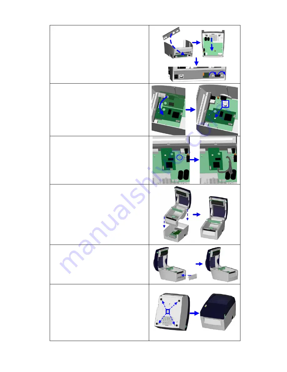
9.
Install the Ethernet Back Panel to the
printer.
10.
al
11.
screws.
Push the mainboard back to origin
position.
Tighten the hexagonal
12. Align the Ethernet module to the Ethernet
port and plug into it.
3. Tighten the secure screw to fix Ethernet
1
module onto the main board.
14. Connect one end of Module Connection
Wire to the main board and the other end
to the Ethernet module.
15.
Put the middle compartment bac
k and
assemble it with bottom compartment of
the printer.
16. Install the Front Cover Plate.
17. Tighten bottom case screws to complete
No
p
XS
THERNET,1" printer command to
rinter for activating the Ethernet connection
function. Please mind that USB port will be
deactivated once the Ethernet connection
function is activated.
the installation.
te
】
【
After the Ethernet module installation is
com leted, please send the
ET,USBE
"^
p
EZ-DT-2/EZ-DT-4 User’s Manual
24
Содержание EZ-DT-2
Страница 1: ...User s Manual EZ DT 2 EZ DT 4 P N 920 012511 03 Rev A 08 2009 ...
Страница 34: ...Appendix 1 EZ DT 2 Certifications EZ DT 2 EZ DT 4 User s Manual 33 ...
Страница 35: ...EZ DT 2 EZ DT 4 User s Manual 34 ...
Страница 36: ...EZ DT 2 EZ DT 4 User s Manual 35 ...
Страница 37: ...EZ DT 2 EZ DT 4 User s Manual 36 ...
Страница 38: ...EZ DT 2 EZ DT 4 User s Manual 37 ...
Страница 39: ...2 EZ DT 4 Certifications EZ DT 2 EZ DT 4 User s Manual 38 ...
Страница 40: ...EZ DT 2 EZ DT 4 User s Manual 39 ...
Страница 41: ...EZ DT 2 EZ DT 4 User s Manual 40 ...
Страница 42: ...EZ DT 2 EZ DT 4 User s Manual 41 ...
Страница 43: ...EZ DT 2 EZ DT 4 User s Manual 42 ...
Страница 44: ...EZ DT 2 EZ DT 4 User s Manual 43 ...


