


22
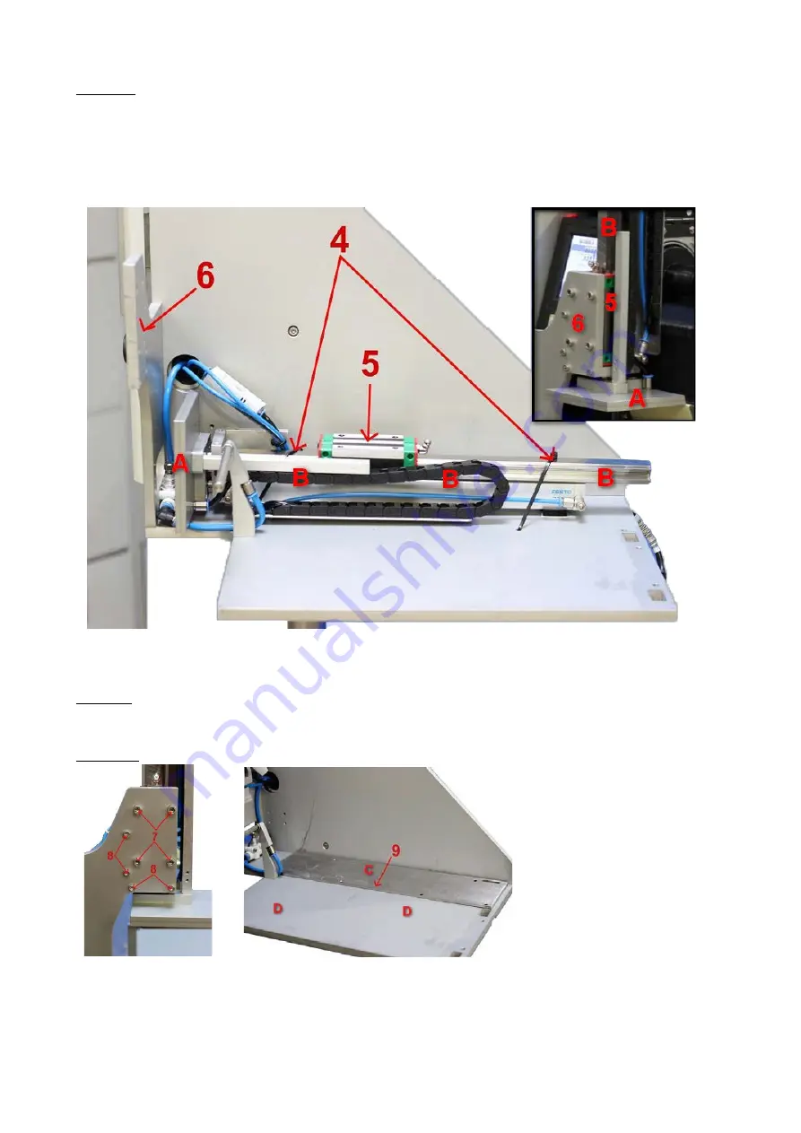
Picture 4:
• Remove the tie wraps (4)
• Move the slide (5) as far as possible towards the applicator head (A)
• Lift up the piston (B) including the slide and tubes and place the slide (5) against surface “6”
Pic. 4
Picture 5: mount the slider to the bracket with 4 bolts M5x16 and tighten properly (step 7) mount
the pneumatic cylinder bracket with 4 bolts M4x16 and tighten properly (step 8)
Picture 6: place adapter plate “C” onto the applicator main frame “D” (step 9)
Pic. 5
Pic. 6
Содержание AG3000
Страница 28: ...28 Pic 7 select the icon shown below to return to main menu Pic 8 Back on main menu ...
Страница 36: ...36 Pictures 2 Picture 3 ...
Страница 43: ...43 10 Wire diagrams 10 1 Power and signals schematic 10 2 Control unit picture ...
Страница 44: ...44 10 3 Power circuits 10 4 Connector rack detailed view ...
Страница 45: ...41 10 5 Connector rack diagram ...
Страница 46: ...42 10 6 Electro pneumatic diagram 10 6 PLC Printer applicator port diagram ...


