Installing the Optional Guy Wires
1. Determine mounting position on ceiling and
establish the angle between 45º-60º for the
cable. Determine correct location on the I-
Beam to drill the hole for the eye bolt. For
example, if the guy wire anchor points on the
fan are 3' 4" (101.6 cm) down from the I-Beam
or Steel Angles the cables should anchor at
least 3' 4" (101.6 cm) away from fan.
2. Install an eye bolt with nuts and washers in I-
beam as per Fig. 14.
3. Measure the run of cable required and cut
approximately 2 FT longer. NOTE: runs longer
than 18 FT will require additional cable.
4.
5.
Secure it with 1 thimble and 2 cable clamps
(Fig.16). Repeat using the other 3 pieces of
guy wire cable, thimbles and cable clamps
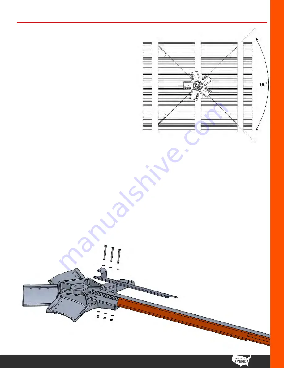
(Fig.15) Guy wires should be snug but not
overstressed to allow free self-levelling. They
should also be approximately 90º apart
(Fig.17).
8. Z-Tech
TM
Blade Assembly
(5) Blades
(5) Blade Stabilizer Plate
(15) 3/8"x16x3.5" Grade 8 Hex Cap Screw
(30) 3/8"x0.812" Grade 8 Flat Washer
(15) 3/8"x16 Grade 8 Nylock Nut
Installing the Blade Assembly
Fig.17
NOTE: Fans hanging lower than 10ft from
where the guy wires will mount may require
additional cable (provided by the installer).
Fig.18
|
1
9
Z-TECH™
FAN
Installation and Technical Operations
®
GO FAN YOURSELF
1. Clamp blade between blade stabilizer
plate and hub.
2. Continue until all 5 blades have been
fastened and tighten to:
30 ft-lbs +/-2 ft-lbs
(40.7 N
.
m = 30 ft-lbs) or
(38 N
.
m to 43.4 N
.
m)
3. Turn the fan by hand and verify
minimum clearance exists for all
blades from all obstructions.


