GBESS 2.4_4.8KWH system user manual
21
PV1
PV2
BUS
GRID
LOAD
DC Switch
ON
OFF
WIFI
TO BAT
CAN
RS485
Ethernet
BUS
TO PV
CAN
BAT
B
A
T
C
H
G
D
IS
C
H
G
Distribution box
Load
Meter for Grid
Emergency load
PV PANEL
Geatom103KHF system
Battery Cabinet
Lead type battery
B5
B6
D3
F3 F4
SET
Single Energy Meter
L
N
L’
N'
5 6 7 8
PV INVERTER
DC
AC
Meter for PV
SE
T
Si
ng
le
E
ne
rg
y
Me
te
r
L
N
L’
N'
5
6
7
8
L
N
K-GRID
To
Meter
DC
BREAKER
To
Inerter
To
Cabinet
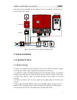
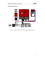
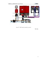
Figure 26 Connecting Demonstration for Lead-type Battery Storage System
1)
The PV power should be lower than 4.2kW;
2)
The emergency load connected should be no more than 2kW;
3)
A 32A/400V AC Breaker and 300mA leakage protector should be installed between the system
and the grid;
4)
A 16A/400V AC Breaker and 300mA leakage protector should be installed between the system
and the emergency load.
3.3.1 How to Make Power Connecting Line
Figure 27~Figure 28 are the connecting demonstration for PV connector, grid connector and
emergency load connector. Please choose the proper wire (AWG12 recommended) to make different
connectors according to the length of connecting line.
L
N
L
N
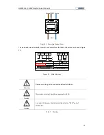
Figure 27 GRID connector(F3) and Wiring
Line definition: the brown is power line(L), the blue is neutral line(N), the yellow green is grounding
line(PE)

