11
221129A
4 H e a t i n g S y s t e m
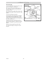
Diagram 4.3
METHOD 1
METHOD 2
METHOD 3
SUPPLY STOP
VALVE
SUPPLY
PIPE
HOSE
UNIONS
SERVICING
VALVE
TEMPORARY
HOSE
HEATING
SYSTEM
HEATING
SYSTEM
TEMPORARY
HOSE
HOSE
UNIONS
SERVICING
VALVE
SUPPLY
PIPE
SUPPLY STOP
VALVE
DOUBLE CHECK
VALVE ASSEMBLY
HEATING
SYSTEM
SERVICING
VALVE
SUPPLY
STOP VALVE
SUPPLY
PIPE
HOSE
UNIONS
DOUBLE CHECK
VALVE ASSEMBLY
OVERFLOW
CISTERN
COMBINED
CHECK VALVE
AND VACUUM
BREAKER
PRESSURE
REDUCING
VALVE
3132
5 D o m e s t i c H o t W a t e r S y s t e m
4.9 Filling Sealed Systems
Provision for filling the system at a low level must be
made. Three methods of filling are shown in
diagram 4.3.
There must be no permanent connection to the mains
water supply, even through a non-return valve.
4.10 Corrosion Inhibitor
If an inhibitor is to be used in the system, contact the
inhibitor manufacturer so that they can recommend their
most suitable product.
When fitting the boiler into an existing system, special
care should be taken to drain the entire system, including
radiators, then thoroughly cleaning out before fitting the
boiler whether or not adding an inhibitor.
4.11 Draining
A draining tap must be provided at the lowest points of
the system, which will allow the entire system to be
drained. An additional draining tap MUST be fitted
close to the boiler.
The flow and return isolation valves are provided with
drain points for boiler heat exchanger drainage.
5.1 General
The domestic hot water service must be in accordance
with the rules in force in the countries of destination.
5.2 Water Pressure
For the minimum and maximum working pressures of
the domestic hot water circuit of the boiler refer to
Section 1.6 Data.
If the cold water supply pressure exceeds the maximum,
a governor must be fitted in the supply to the boiler to
reduce the pressure to within the limits given.
5.3 “Hard” Water Areas
In areas where the water is “hard”, more than
200mg/litre, it is recommended that a proprietary scale
reducer is fitted in the cold water supply to the boiler.
Check the total water “hardness”, using the kit supplied,
in the door, following the instructions given. Consult the
local water company for additional advice.
A double check valve assembly must be fitted upstream
of the scale reducer. For the relative position of the scale
reducer and pressure reducing valve, if required, refer to
the manufacturer’s instructions.


