


37
12 Commissioning
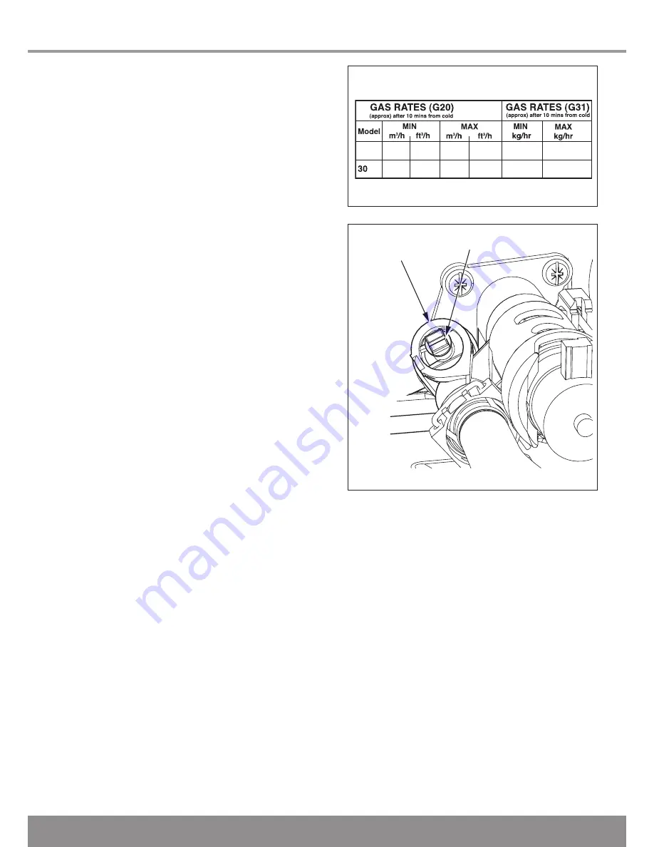
12.6 Gas Rate
The gas valve is factory set for natural gas (G20) and should
need no adjustment.
Should any doubt exist about the gas rate, check it using the
gas meter test dial and stop watch, at least 10 minutes after
the burner has lit, see diagram 12.3 for approximate rates.
Make sure that all other gas burning appliances and pilot
lights are off.
It should be noted that this appliance will modulate the heat
input according to demand. This may affect the gas rates
measured if the appliance reaches its operating temperature
during the measurement.
Disconnect the pressure gauge and close the screw.
NOTE: The burner pressure cannot be
measured at the gas valve as it is altered by
the suction of the fan and modulated according
to demand.
Adjusting the gas valve requires a combustion analyser and
should only be carried out by a
competent person
, but in
the unlikely event that the gas valve needs adjusting, refer to
section 13.7.
Flue Gases:
If any doubt exists that the flue products are not
exhausting correctly, investigate by use of a flue gas analyser
(FGA).
12.7 Heating Systems
Ensure that the external controls are calling for heat.
Fully open all radiator valves, flow control valve, if fitted, see
diagram 5.1.
Switch on the appliance and ensure that the central heating is
calling for heat.
Balance the radiators as required and if fitted adjust valve to
give the required system differential. Turn off all radiators that
can be shut off by the user and check to see if less than the
maximum differential allowed of 20
o
C can be achieved across
flow and return.
NOTE:
Should the system require that the appliance has to
be adjusted, the front will need to be removed, as described
in the servicing section 13, and the control box lowered into
its service position.
The appliance pump has two speeds and can be adjusted
depending on the requirements of the system.
The appliance has an inbuilt automatic adjustable bypass
valve. The pressure can be adjusted between approx 1.5
and 3.5mH
2
O but is factory pre-set to approx 2.5mH
2
O.
The pressure changes by approx 0.1mH
2
O for each full turn
of the bypass screw, see diagram 12.4. Turning clockwise
increases the pressure and turning anti-clockwise decreases
the pressure.
Allow the system to reach maximum temperature then switch
off the boiler by isolating from the electrical supply.
Drain the entire system rapidly whilst hot, using the drain taps
at all the low points of the system. Fill and vent the system
as described previously.
Lock or remove the handle from control valve, if fitted.
Adjust the boiler temperature controls and any system
controls to their required settings.
AUTOMATIC
BYPASS VALVE
BYPASS SCREW
13234
Diagram 12.4
13866
Diagram 12.3
sxi
sxi 0.53
0.53
18.7
18.7
2.0
2.0
71.0
107.0
0.39
0.41
1.47
2.22
18
Содержание 18sxi
Страница 30: ...30 10 Twin Flue Length Preparation and Installation Diagram 10 24 13226...
Страница 46: ...46 14 Fault Finding 13012 Diagram 14 5 CENTRAL HEATING...
Страница 48: ...48 14 Fault Finding 13447 Diagram 14 6 Fault Codes continued...
Страница 61: ...61 16 Spare Parts Diagram 15 21 13861 1 2 3 4 5 7 9 10 12 6 8 11 13...
Страница 63: ...63...