12
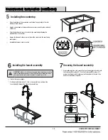
Pull
down
Squeeze
1
1
2
8
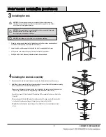
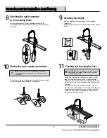
Installing the soap dispenser
From under the sink, screw the soap dispenser (T) onto the
soap assembly (O) shank. Insert the soap pump (Q) down
into the soap assembly (O).
Insert the soap assembly (O) through the selected hole
in the sink. Secure the soap assembly(O) to the sink with
9
Making the water supply connections
Thread the nut (1) on the supply line onto the outlet of the
water supply valve (2) and tighten with a wrench. Do not
overtighten.
NOTE: The hot side inlet tube is indicated by a label. Avoid
twisting wires together or placing the wires close to each
other and damaging.
Q
Topmount Installation (continued)
13
HOMEDEPOT.COM/GLACIERBAY
Undermount Installation (continued)
12
Making the water supply connections
Thread the nut (1) on the supply line onto the outlet of the
water supply valve (2) and tighten with a wrench. Do not
NOTE: The hot side inlet tube is indicated by a label. Avoid
twisting wires together or placing the wires close to each
Making the water supply connections
Thread the nut (1) on the supply line onto the outlet of the
water supply valve (2) and tighten with a wrench. Do not
NOTE: The hot side inlet tube is indicated by a label. Avoid
twisting wires together or placing the wires close to each
Making the water supply connections
Thread the nut (1) on the supply line onto the outlet of the
water supply valve (2) and tighten with a wrench. Do not
NOTE: The hot side inlet tube is indicated by a label. Avoid
twisting wires together or placing the wires close to each
Making the water supply connections
Thread the nut (1) on the supply line onto the outlet of the
water supply valve (2) and tighten with a wrench. Do not
NOTE: The hot side inlet tube is indicated by a label. Avoid
twisting wires together or placing the wires close to each
Making the water supply connections
Thread the nut (1) on the supply line onto the outlet of the
water supply valve (2) and tighten with a wrench. Do not
NOTE: The hot side inlet tube is indicated by a label. Avoid
twisting wires together or placing the wires close to each
Making the water supply connections
Thread the nut (1) on the supply line onto the outlet of the
water supply valve (2) and tighten with a wrench. Do not
NOTE: The hot side inlet tube is indicated by a label. Avoid
twisting wires together or placing the wires close to each
Making the water supply connections
Thread the nut (1) on the supply line onto the outlet of the
water supply valve (2) and tighten with a wrench. Do not
NOTE: The hot side inlet tube is indicated by a label. Avoid
twisting wires together or placing the wires close to each
Making the water supply connections
Thread the nut (1) on the supply line onto the outlet of the
water supply valve (2) and tighten with a wrench. Do not
NOTE: The hot side inlet tube is indicated by a label. Avoid
twisting wires together or placing the wires close to each
Making the water supply connections
Thread the nut (1) on the supply line onto the outlet of the
water supply valve (2) and tighten with a wrench. Do not
NOTE: The hot side inlet tube is indicated by a label. Avoid
twisting wires together or placing the wires close to each
Making the water supply connections
Thread the nut (1) on the supply line onto the outlet of the
water supply valve (2) and tighten with a wrench. Do not
NOTE: The hot side inlet tube is indicated by a label. Avoid
twisting wires together or placing the wires close to each
Making the water supply connections
Thread the nut (1) on the supply line onto the outlet of the
water supply valve (2) and tighten with a wrench. Do not
NOTE: The hot side inlet tube is indicated by a label. Avoid
twisting wires together or placing the wires close to each
Making the water supply connections
Thread the nut (1) on the supply line onto the outlet of the
water supply valve (2) and tighten with a wrench. Do not
NOTE: The hot side inlet tube is indicated by a label. Avoid
twisting wires together or placing the wires close to each
Making the water supply connections
Thread the nut (1) on the supply line onto the outlet of the
water supply valve (2) and tighten with a wrench. Do not
NOTE: The hot side inlet tube is indicated by a label. Avoid
twisting wires together or placing the wires close to each
Making the water supply connections
Thread the nut (1) on the supply line onto the outlet of the
water supply valve (2) and tighten with a wrench. Do not
NOTE: The hot side inlet tube is indicated by a label. Avoid
twisting wires together or placing the wires close to each
Making the water supply connections
Thread the nut (1) on the supply line onto the outlet of the
water supply valve (2) and tighten with a wrench. Do not
NOTE: The hot side inlet tube is indicated by a label. Avoid
twisting wires together or placing the wires close to each
Making the water supply connections
Thread the nut (1) on the supply line onto the outlet of the
water supply valve (2) and tighten with a wrench. Do not
NOTE: The hot side inlet tube is indicated by a label. Avoid
twisting wires together or placing the wires close to each
Making the water supply connections
Thread the nut (1) on the supply line onto the outlet of the
water supply valve (2) and tighten with a wrench. Do not
NOTE: The hot side inlet tube is indicated by a label. Avoid
twisting wires together or placing the wires close to each
Making the water supply connections
Thread the nut (1) on the supply line onto the outlet of the
water supply valve (2) and tighten with a wrench. Do not
NOTE: The hot side inlet tube is indicated by a label. Avoid
twisting wires together or placing the wires close to each
Making the water supply connections
Thread the nut (1) on the supply line onto the outlet of the
water supply valve (2) and tighten with a wrench. Do not
NOTE: The hot side inlet tube is indicated by a label. Avoid
twisting wires together or placing the wires close to each
Making the water supply connections
Thread the nut (1) on the supply line onto the outlet of the
water supply valve (2) and tighten with a wrench. Do not
NOTE: The hot side inlet tube is indicated by a label. Avoid
twisting wires together or placing the wires close to each
Making the water supply connections
Thread the nut (1) on the supply line onto the outlet of the
water supply valve (2) and tighten with a wrench. Do not
NOTE: The hot side inlet tube is indicated by a label. Avoid
twisting wires together or placing the wires close to each
Making the water supply connections
Thread the nut (1) on the supply line onto the outlet of the
water supply valve (2) and tighten with a wrench. Do not
NOTE: The hot side inlet tube is indicated by a label. Avoid
twisting wires together or placing the wires close to each
Making the water supply connections
Thread the nut (1) on the supply line onto the outlet of the
water supply valve (2) and tighten with a wrench. Do not
NOTE: The hot side inlet tube is indicated by a label. Avoid
twisting wires together or placing the wires close to each
Making the water supply connections
Thread the nut (1) on the supply line onto the outlet of the
water supply valve (2) and tighten with a wrench. Do not
NOTE: The hot side inlet tube is indicated by a label. Avoid
twisting wires together or placing the wires close to each
Making the water supply connections
Thread the nut (1) on the supply line onto the outlet of the
water supply valve (2) and tighten with a wrench. Do not
NOTE: The hot side inlet tube is indicated by a label. Avoid
twisting wires together or placing the wires close to each
Making the water supply connections
Thread the nut (1) on the supply line onto the outlet of the
water supply valve (2) and tighten with a wrench. Do not
NOTE: The hot side inlet tube is indicated by a label. Avoid
twisting wires together or placing the wires close to each
Making the water supply connections
Thread the nut (1) on the supply line onto the outlet of the
water supply valve (2) and tighten with a wrench. Do not
NOTE: The hot side inlet tube is indicated by a label. Avoid
twisting wires together or placing the wires close to each
Making the water supply connections
Thread the nut (1) on the supply line onto the outlet of the
water supply valve (2) and tighten with a wrench. Do not
NOTE: The hot side inlet tube is indicated by a label. Avoid
twisting wires together or placing the wires close to each
Making the water supply connections
Thread the nut (1) on the supply line onto the outlet of the
water supply valve (2) and tighten with a wrench. Do not
NOTE: The hot side inlet tube is indicated by a label. Avoid
twisting wires together or placing the wires close to each
Making the water supply connections
Thread the nut (1) on the supply line onto the outlet of the
water supply valve (2) and tighten with a wrench. Do not
NOTE: The hot side inlet tube is indicated by a label. Avoid
twisting wires together or placing the wires close to each
Making the water supply connections
Thread the nut (1) on the supply line onto the outlet of the
water supply valve (2) and tighten with a wrench. Do not
NOTE: The hot side inlet tube is indicated by a label. Avoid
twisting wires together or placing the wires close to each
Making the water supply connections
Thread the nut (1) on the supply line onto the outlet of the
water supply valve (2) and tighten with a wrench. Do not
NOTE: The hot side inlet tube is indicated by a label. Avoid
twisting wires together or placing the wires close to each
Making the water supply connections
Thread the nut (1) on the supply line onto the outlet of the
water supply valve (2) and tighten with a wrench. Do not
NOTE: The hot side inlet tube is indicated by a label. Avoid
twisting wires together or placing the wires close to each
Making the water supply connections
Thread the nut (1) on the supply line onto the outlet of the
water supply valve (2) and tighten with a wrench. Do not
NOTE: The hot side inlet tube is indicated by a label. Avoid
twisting wires together or placing the wires close to each
Making the water supply connections
Thread the nut (1) on the supply line onto the outlet of the
water supply valve (2) and tighten with a wrench. Do not
NOTE: The hot side inlet tube is indicated by a label. Avoid
twisting wires together or placing the wires close to each
Making the water supply connections
Thread the nut (1) on the supply line onto the outlet of the
water supply valve (2) and tighten with a wrench. Do not
NOTE: The hot side inlet tube is indicated by a label. Avoid
twisting wires together or placing the wires close to each
Making the water supply connections
Thread the nut (1) on the supply line onto the outlet of the
water supply valve (2) and tighten with a wrench. Do not
NOTE: The hot side inlet tube is indicated by a label. Avoid
twisting wires together or placing the wires close to each
Making the water supply connections
Thread the nut (1) on the supply line onto the outlet of the
water supply valve (2) and tighten with a wrench. Do not
NOTE: The hot side inlet tube is indicated by a label. Avoid
twisting wires together or placing the wires close to each
Making the water supply connections
Thread the nut (1) on the supply line onto the outlet of the
water supply valve (2) and tighten with a wrench. Do not
NOTE: The hot side inlet tube is indicated by a label. Avoid
twisting wires together or placing the wires close to each
Making the water supply connections
Thread the nut (1) on the supply line onto the outlet of the
water supply valve (2) and tighten with a wrench. Do not
NOTE: The hot side inlet tube is indicated by a label. Avoid
twisting wires together or placing the wires close to each
Making the water supply connections
Thread the nut (1) on the supply line onto the outlet of the
water supply valve (2) and tighten with a wrench. Do not
NOTE: The hot side inlet tube is indicated by a label. Avoid
twisting wires together or placing the wires close to each
Making the water supply connections
Thread the nut (1) on the supply line onto the outlet of the
water supply valve (2) and tighten with a wrench. Do not
NOTE: The hot side inlet tube is indicated by a label. Avoid
twisting wires together or placing the wires close to each
Making the water supply connections
Thread the nut (1) on the supply line onto the outlet of the
water supply valve (2) and tighten with a wrench. Do not
NOTE: The hot side inlet tube is indicated by a label. Avoid
twisting wires together or placing the wires close to each
Making the water supply connections
Thread the nut (1) on the supply line onto the outlet of the
water supply valve (2) and tighten with a wrench. Do not
NOTE: The hot side inlet tube is indicated by a label. Avoid
twisting wires together or placing the wires close to each
Making the water supply connections
Thread the nut (1) on the supply line onto the outlet of the
water supply valve (2) and tighten with a wrench. Do not
NOTE: The hot side inlet tube is indicated by a label. Avoid
twisting wires together or placing the wires close to each
Making the water supply connections
Thread the nut (1) on the supply line onto the outlet of the
water supply valve (2) and tighten with a wrench. Do not
NOTE: The hot side inlet tube is indicated by a label. Avoid
twisting wires together or placing the wires close to each
Making the water supply connections
Thread the nut (1) on the supply line onto the outlet of the
water supply valve (2) and tighten with a wrench. Do not
NOTE: The hot side inlet tube is indicated by a label. Avoid
twisting wires together or placing the wires close to each
Making the water supply connections
Thread the nut (1) on the supply line onto the outlet of the
water supply valve (2) and tighten with a wrench. Do not
NOTE: The hot side inlet tube is indicated by a label. Avoid
twisting wires together or placing the wires close to each
Making the water supply connections
Thread the nut (1) on the supply line onto the outlet of the
water supply valve (2) and tighten with a wrench. Do not
NOTE: The hot side inlet tube is indicated by a label. Avoid
twisting wires together or placing the wires close to each
Making the water supply connections
Thread the nut (1) on the supply line onto the outlet of the
water supply valve (2) and tighten with a wrench. Do not
NOTE: The hot side inlet tube is indicated by a label. Avoid
twisting wires together or placing the wires close to each
Making the water supply connections
Thread the nut (1) on the supply line onto the outlet of the
water supply valve (2) and tighten with a wrench. Do not
NOTE: The hot side inlet tube is indicated by a label. Avoid
twisting wires together or placing the wires close to each
Making the water supply connections
Thread the nut (1) on the supply line onto the outlet of the
water supply valve (2) and tighten with a wrench. Do not
NOTE: The hot side inlet tube is indicated by a label. Avoid
twisting wires together or placing the wires close to each
Making the water supply connections
Thread the nut (1) on the supply line onto the outlet of the
water supply valve (2) and tighten with a wrench. Do not
NOTE: The hot side inlet tube is indicated by a label. Avoid
twisting wires together or placing the wires close to each
Making the water supply connections
Thread the nut (1) on the supply line onto the outlet of the
water supply valve (2) and tighten with a wrench. Do not
NOTE: The hot side inlet tube is indicated by a label. Avoid
twisting wires together or placing the wires close to each
Making the water supply connections
Thread the nut (1) on the supply line onto the outlet of the
water supply valve (2) and tighten with a wrench. Do not
NOTE: The hot side inlet tube is indicated by a label. Avoid
twisting wires together or placing the wires close to each
Making the water supply connections
Thread the nut (1) on the supply line onto the outlet of the
water supply valve (2) and tighten with a wrench. Do not
NOTE: The hot side inlet tube is indicated by a label. Avoid
twisting wires together or placing the wires close to each
Making the water supply connections
Thread the nut (1) on the supply line onto the outlet of the
water supply valve (2) and tighten with a wrench. Do not
NOTE: The hot side inlet tube is indicated by a label. Avoid
twisting wires together or placing the wires close to each
Making the water supply connections
Thread the nut (1) on the supply line onto the outlet of the
water supply valve (2) and tighten with a wrench. Do not
NOTE: The hot side inlet tube is indicated by a label. Avoid
twisting wires together or placing the wires close to each
Making the water supply connections
Thread the nut (1) on the supply line onto the outlet of the
water supply valve (2) and tighten with a wrench. Do not
NOTE: The hot side inlet tube is indicated by a label. Avoid
twisting wires together or placing the wires close to each
Making the water supply connections
Thread the nut (1) on the supply line onto the outlet of the
water supply valve (2) and tighten with a wrench. Do not
NOTE: The hot side inlet tube is indicated by a label. Avoid
twisting wires together or placing the wires close to each
Making the water supply connections
Thread the nut (1) on the supply line onto the outlet of the
water supply valve (2) and tighten with a wrench. Do not
NOTE: The hot side inlet tube is indicated by a label. Avoid
twisting wires together or placing the wires close to each
Making the water supply connections
Thread the nut (1) on the supply line onto the outlet of the
water supply valve (2) and tighten with a wrench. Do not
NOTE: The hot side inlet tube is indicated by a label. Avoid
twisting wires together or placing the wires close to each
Making the water supply connections
Thread the nut (1) on the supply line onto the outlet of the
water supply valve (2) and tighten with a wrench. Do not
NOTE: The hot side inlet tube is indicated by a label. Avoid
twisting wires together or placing the wires close to each
1
Making the water supply connections
Thread the nut (1) on the supply line onto the outlet of the
water supply valve (2) and tighten with a wrench. Do not
NOTE: The hot side inlet tube is indicated by a label. Avoid
twisting wires together or placing the wires close to each
Making the water supply connections
Thread the nut (1) on the supply line onto the outlet of the
water supply valve (2) and tighten with a wrench. Do not
NOTE: The hot side inlet tube is indicated by a label. Avoid
twisting wires together or placing the wires close to each
Making the water supply connections
Thread the nut (1) on the supply line onto the outlet of the
water supply valve (2) and tighten with a wrench. Do not
NOTE: The hot side inlet tube is indicated by a label. Avoid
twisting wires together or placing the wires close to each
Making the water supply connections
Thread the nut (1) on the supply line onto the outlet of the
water supply valve (2) and tighten with a wrench. Do not
NOTE: The hot side inlet tube is indicated by a label. Avoid
twisting wires together or placing the wires close to each
Making the water supply connections
Thread the nut (1) on the supply line onto the outlet of the
water supply valve (2) and tighten with a wrench. Do not
NOTE: The hot side inlet tube is indicated by a label. Avoid
twisting wires together or placing the wires close to each
Making the water supply connections
Thread the nut (1) on the supply line onto the outlet of the
water supply valve (2) and tighten with a wrench. Do not
NOTE: The hot side inlet tube is indicated by a label. Avoid
twisting wires together or placing the wires close to each
Making the water supply connections
Thread the nut (1) on the supply line onto the outlet of the
water supply valve (2) and tighten with a wrench. Do not
NOTE: The hot side inlet tube is indicated by a label. Avoid
twisting wires together or placing the wires close to each
Making the water supply connections
Thread the nut (1) on the supply line onto the outlet of the
water supply valve (2) and tighten with a wrench. Do not
NOTE: The hot side inlet tube is indicated by a label. Avoid
twisting wires together or placing the wires close to each
Making the water supply connections
Thread the nut (1) on the supply line onto the outlet of the
water supply valve (2) and tighten with a wrench. Do not
NOTE: The hot side inlet tube is indicated by a label. Avoid
twisting wires together or placing the wires close to each
Making the water supply connections
Thread the nut (1) on the supply line onto the outlet of the
water supply valve (2) and tighten with a wrench. Do not
NOTE: The hot side inlet tube is indicated by a label. Avoid
twisting wires together or placing the wires close to each
Making the water supply connections
Thread the nut (1) on the supply line onto the outlet of the
water supply valve (2) and tighten with a wrench. Do not
NOTE: The hot side inlet tube is indicated by a label. Avoid
twisting wires together or placing the wires close to each
Making the water supply connections
Thread the nut (1) on the supply line onto the outlet of the
water supply valve (2) and tighten with a wrench. Do not
NOTE: The hot side inlet tube is indicated by a label. Avoid
twisting wires together or placing the wires close to each
Making the water supply connections
Thread the nut (1) on the supply line onto the outlet of the
water supply valve (2) and tighten with a wrench. Do not
NOTE: The hot side inlet tube is indicated by a label. Avoid
twisting wires together or placing the wires close to each
Making the water supply connections
Thread the nut (1) on the supply line onto the outlet of the
water supply valve (2) and tighten with a wrench. Do not
NOTE: The hot side inlet tube is indicated by a label. Avoid
twisting wires together or placing the wires close to each
Making the water supply connections
Thread the nut (1) on the supply line onto the outlet of the
water supply valve (2) and tighten with a wrench. Do not
NOTE: The hot side inlet tube is indicated by a label. Avoid
twisting wires together or placing the wires close to each
Making the water supply connections
Thread the nut (1) on the supply line onto the outlet of the
water supply valve (2) and tighten with a wrench. Do not
NOTE: The hot side inlet tube is indicated by a label. Avoid
twisting wires together or placing the wires close to each
Making the water supply connections
Thread the nut (1) on the supply line onto the outlet of the
water supply valve (2) and tighten with a wrench. Do not
NOTE: The hot side inlet tube is indicated by a label. Avoid
twisting wires together or placing the wires close to each
Making the water supply connections
Thread the nut (1) on the supply line onto the outlet of the
water supply valve (2) and tighten with a wrench. Do not
NOTE: The hot side inlet tube is indicated by a label. Avoid
twisting wires together or placing the wires close to each
Making the water supply connections
Thread the nut (1) on the supply line onto the outlet of the
water supply valve (2) and tighten with a wrench. Do not
NOTE: The hot side inlet tube is indicated by a label. Avoid
twisting wires together or placing the wires close to each
Making the water supply connections
Thread the nut (1) on the supply line onto the outlet of the
water supply valve (2) and tighten with a wrench. Do not
NOTE: The hot side inlet tube is indicated by a label. Avoid
twisting wires together or placing the wires close to each
Making the water supply connections
Thread the nut (1) on the supply line onto the outlet of the
water supply valve (2) and tighten with a wrench. Do not
NOTE: The hot side inlet tube is indicated by a label. Avoid
twisting wires together or placing the wires close to each
Making the water supply connections
Thread the nut (1) on the supply line onto the outlet of the
water supply valve (2) and tighten with a wrench. Do not
NOTE: The hot side inlet tube is indicated by a label. Avoid
twisting wires together or placing the wires close to each
Making the water supply connections
Thread the nut (1) on the supply line onto the outlet of the
water supply valve (2) and tighten with a wrench. Do not
NOTE: The hot side inlet tube is indicated by a label. Avoid
twisting wires together or placing the wires close to each
Making the water supply connections
Thread the nut (1) on the supply line onto the outlet of the
water supply valve (2) and tighten with a wrench. Do not
NOTE: The hot side inlet tube is indicated by a label. Avoid
twisting wires together or placing the wires close to each
Making the water supply connections
Thread the nut (1) on the supply line onto the outlet of the
water supply valve (2) and tighten with a wrench. Do not
NOTE: The hot side inlet tube is indicated by a label. Avoid
twisting wires together or placing the wires close to each
Making the water supply connections
Thread the nut (1) on the supply line onto the outlet of the
water supply valve (2) and tighten with a wrench. Do not
NOTE: The hot side inlet tube is indicated by a label. Avoid
twisting wires together or placing the wires close to each
Making the water supply connections
Thread the nut (1) on the supply line onto the outlet of the
water supply valve (2) and tighten with a wrench. Do not
NOTE: The hot side inlet tube is indicated by a label. Avoid
twisting wires together or placing the wires close to each
Making the water supply connections
Thread the nut (1) on the supply line onto the outlet of the
water supply valve (2) and tighten with a wrench. Do not
NOTE: The hot side inlet tube is indicated by a label. Avoid
twisting wires together or placing the wires close to each
Making the water supply connections
Thread the nut (1) on the supply line onto the outlet of the
water supply valve (2) and tighten with a wrench. Do not
NOTE: The hot side inlet tube is indicated by a label. Avoid
twisting wires together or placing the wires close to each
Making the water supply connections
Thread the nut (1) on the supply line onto the outlet of the
water supply valve (2) and tighten with a wrench. Do not
NOTE: The hot side inlet tube is indicated by a label. Avoid
twisting wires together or placing the wires close to each
Making the water supply connections
Thread the nut (1) on the supply line onto the outlet of the
water supply valve (2) and tighten with a wrench. Do not
NOTE: The hot side inlet tube is indicated by a label. Avoid
twisting wires together or placing the wires close to each
Making the water supply connections
Thread the nut (1) on the supply line onto the outlet of the
water supply valve (2) and tighten with a wrench. Do not
NOTE: The hot side inlet tube is indicated by a label. Avoid
twisting wires together or placing the wires close to each
Making the water supply connections
Thread the nut (1) on the supply line onto the outlet of the
water supply valve (2) and tighten with a wrench. Do not
NOTE: The hot side inlet tube is indicated by a label. Avoid
twisting wires together or placing the wires close to each
Making the water supply connections
Thread the nut (1) on the supply line onto the outlet of the
water supply valve (2) and tighten with a wrench. Do not
NOTE: The hot side inlet tube is indicated by a label. Avoid
twisting wires together or placing the wires close to each
Making the water supply connections
Thread the nut (1) on the supply line onto the outlet of the
water supply valve (2) and tighten with a wrench. Do not
NOTE: The hot side inlet tube is indicated by a label. Avoid
twisting wires together or placing the wires close to each
Making the water supply connections
Thread the nut (1) on the supply line onto the outlet of the
water supply valve (2) and tighten with a wrench. Do not
NOTE: The hot side inlet tube is indicated by a label. Avoid
twisting wires together or placing the wires close to each
Making the water supply connections
Thread the nut (1) on the supply line onto the outlet of the
water supply valve (2) and tighten with a wrench. Do not
NOTE: The hot side inlet tube is indicated by a label. Avoid
twisting wires together or placing the wires close to each
Making the water supply connections
Thread the nut (1) on the supply line onto the outlet of the
water supply valve (2) and tighten with a wrench. Do not
NOTE: The hot side inlet tube is indicated by a label. Avoid
twisting wires together or placing the wires close to each
Making the water supply connections
Thread the nut (1) on the supply line onto the outlet of the
water supply valve (2) and tighten with a wrench. Do not
NOTE: The hot side inlet tube is indicated by a label. Avoid
twisting wires together or placing the wires close to each
Making the water supply connections
Thread the nut (1) on the supply line onto the outlet of the
water supply valve (2) and tighten with a wrench. Do not
NOTE: The hot side inlet tube is indicated by a label. Avoid
twisting wires together or placing the wires close to each
Making the water supply connections
Thread the nut (1) on the supply line onto the outlet of the
water supply valve (2) and tighten with a wrench. Do not
NOTE: The hot side inlet tube is indicated by a label. Avoid
twisting wires together or placing the wires close to each
Making the water supply connections
Thread the nut (1) on the supply line onto the outlet of the
water supply valve (2) and tighten with a wrench. Do not
NOTE: The hot side inlet tube is indicated by a label. Avoid
twisting wires together or placing the wires close to each
Making the water supply connections
Thread the nut (1) on the supply line onto the outlet of the
water supply valve (2) and tighten with a wrench. Do not
NOTE: The hot side inlet tube is indicated by a label. Avoid
twisting wires together or placing the wires close to each
Making the water supply connections
Thread the nut (1) on the supply line onto the outlet of the
water supply valve (2) and tighten with a wrench. Do not
NOTE: The hot side inlet tube is indicated by a label. Avoid
twisting wires together or placing the wires close to each
Making the water supply connections
Thread the nut (1) on the supply line onto the outlet of the
water supply valve (2) and tighten with a wrench. Do not
NOTE: The hot side inlet tube is indicated by a label. Avoid
twisting wires together or placing the wires close to each
Making the water supply connections
Thread the nut (1) on the supply line onto the outlet of the
water supply valve (2) and tighten with a wrench. Do not
NOTE: The hot side inlet tube is indicated by a label. Avoid
twisting wires together or placing the wires close to each
Making the water supply connections
Thread the nut (1) on the supply line onto the outlet of the
water supply valve (2) and tighten with a wrench. Do not
NOTE: The hot side inlet tube is indicated by a label. Avoid
twisting wires together or placing the wires close to each
Making the water supply connections
Thread the nut (1) on the supply line onto the outlet of the
water supply valve (2) and tighten with a wrench. Do not
NOTE: The hot side inlet tube is indicated by a label. Avoid
twisting wires together or placing the wires close to each
Making the water supply connections
Thread the nut (1) on the supply line onto the outlet of the
water supply valve (2) and tighten with a wrench. Do not
NOTE: The hot side inlet tube is indicated by a label. Avoid
twisting wires together or placing the wires close to each
Making the water supply connections
Thread the nut (1) on the supply line onto the outlet of the
water supply valve (2) and tighten with a wrench. Do not
NOTE: The hot side inlet tube is indicated by a label. Avoid
twisting wires together or placing the wires close to each
Making the water supply connections
Thread the nut (1) on the supply line onto the outlet of the
water supply valve (2) and tighten with a wrench. Do not
NOTE: The hot side inlet tube is indicated by a label. Avoid
twisting wires together or placing the wires close to each
Making the water supply connections
Thread the nut (1) on the supply line onto the outlet of the
water supply valve (2) and tighten with a wrench. Do not
NOTE: The hot side inlet tube is indicated by a label. Avoid
twisting wires together or placing the wires close to each
Making the water supply connections
Thread the nut (1) on the supply line onto the outlet of the
water supply valve (2) and tighten with a wrench. Do not
NOTE: The hot side inlet tube is indicated by a label. Avoid
twisting wires together or placing the wires close to each
Making the water supply connections
Thread the nut (1) on the supply line onto the outlet of the
water supply valve (2) and tighten with a wrench. Do not
NOTE: The hot side inlet tube is indicated by a label. Avoid
twisting wires together or placing the wires close to each
Making the water supply connections
Thread the nut (1) on the supply line onto the outlet of the
water supply valve (2) and tighten with a wrench. Do not
NOTE: The hot side inlet tube is indicated by a label. Avoid
twisting wires together or placing the wires close to each
Making the water supply connections
Thread the nut (1) on the supply line onto the outlet of the
water supply valve (2) and tighten with a wrench. Do not
NOTE: The hot side inlet tube is indicated by a label. Avoid
twisting wires together or placing the wires close to each
Making the water supply connections
Thread the nut (1) on the supply line onto the outlet of the
water supply valve (2) and tighten with a wrench. Do not
NOTE: The hot side inlet tube is indicated by a label. Avoid
twisting wires together or placing the wires close to each
Making the water supply connections
Thread the nut (1) on the supply line onto the outlet of the
water supply valve (2) and tighten with a wrench. Do not
NOTE: The hot side inlet tube is indicated by a label. Avoid
twisting wires together or placing the wires close to each
Making the water supply connections
Thread the nut (1) on the supply line onto the outlet of the
water supply valve (2) and tighten with a wrench. Do not
NOTE: The hot side inlet tube is indicated by a label. Avoid
twisting wires together or placing the wires close to each
Making the water supply connections
Thread the nut (1) on the supply line onto the outlet of the
water supply valve (2) and tighten with a wrench. Do not
NOTE: The hot side inlet tube is indicated by a label. Avoid
twisting wires together or placing the wires close to each
Making the water supply connections
Thread the nut (1) on the supply line onto the outlet of the
water supply valve (2) and tighten with a wrench. Do not
NOTE: The hot side inlet tube is indicated by a label. Avoid
twisting wires together or placing the wires close to each
Making the water supply connections
Thread the nut (1) on the supply line onto the outlet of the
water supply valve (2) and tighten with a wrench. Do not
NOTE: The hot side inlet tube is indicated by a label. Avoid
twisting wires together or placing the wires close to each
Making the water supply connections
Thread the nut (1) on the supply line onto the outlet of the
water supply valve (2) and tighten with a wrench. Do not
NOTE: The hot side inlet tube is indicated by a label. Avoid
twisting wires together or placing the wires close to each
Making the water supply connections
Thread the nut (1) on the supply line onto the outlet of the
water supply valve (2) and tighten with a wrench. Do not
NOTE: The hot side inlet tube is indicated by a label. Avoid
twisting wires together or placing the wires close to each
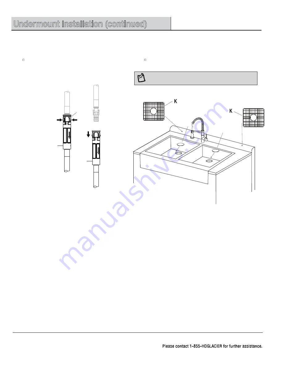
NOTE:
The strainer covers are only included for SKUs showed in page 5 & 7.
M
M
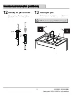
When finished, place the sink grids (K) and strainer cover (M) into the sink.
Installing the grids
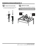
Removing the quick connector
If it is necessary to remove the quick connector (1), squeeze
the tabs (2) on the quick connector and then pull down to
disconnect.
Содержание FSUZAS2721A1SA1
Страница 1: ... Monday Friday V1 TAP 1 SKU Model Please refer to page 4 7 ...
Страница 15: ... Monday Friday ...


