background image

2-3

Installation

2

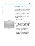
Armlock Removal

Armlock Removal

The armlock on the liquid handler secures the Y-arm

during shipment. You must remove the armlock

prior to installing the Z-arm and operating the

instrument. If the armlock is not removed, the

liquid handler cannot move in the X-direction. This

results in an error state during operation.

If you need to move the liquid handler, always

reinstall the armlock. This safeguards against

mechanical damage.

To remove the armlock:

1 Remove the cardboard label in front of the

armlock.

2 Using the 9/64" ball driver, loosen the

tensioning screw that immobilizes the Y-arm.

3 Using the 9/64" ball driver, remove the two

remaining screws that hold the armlock in

place.

4 Remove the armlock and store it and the ball

driver for future use.

Содержание Quad-Z 215

Страница 1: ...Quad Z 215 Liquid Handler User s Guide LT2545 2003 Gilson Inc All rights reserved April 2003...

Страница 2: ......

Страница 3: ...ide Inserts 2 6 Installing the Probes 2 6 Plumbing Connections 2 7 Transfer Tubing Installation 2 7 Installing the Level Sensing Cables 2 8 Rinse Station and Drain Waste Tubing Installation 2 9 Rack S...

Страница 4: ...ase 3 13 Safety Contact 3 14 Bearing Life 3 14 Sound and Display 3 15 Emergency Contact 3 15 Testing the Liquid Handler s Contacts 3 16 4 Maintenance Helpful Hints 4 2 Cleaning 4 3 Cleaning the Liquid...

Страница 5: ...A 1 Control Software A 2 Probe Guide Inserts A 2 Transfer Tubing and Waste Bottle A 2 Rinse Station A 3 Rack Accessories A 3 Cables and I O Accessories A 4 Miscellaneous A 4 Appendix B Racks Peltier R...

Страница 6: ......

Страница 7: ...nue des Entrepreneurs B P 145 F 95400 Villiers le Bel France Type of Equipment Laboratory Equipment Model Quad Z 215 Liquid Handler Beginning with Serial Number 250A1K001 Month and Year of Manufacture...

Страница 8: ......

Страница 9: ...y contain a dangerous substance use the safety shield included with the instrument and do not interfere in the work area of the instrument until the liquid handler has completed its procedures If dang...

Страница 10: ...allowing access to virtually any tube vial or microplate configuration The optional 849 Multiple Injection Module can be configured with four sample loops of varying capacities to provide complete fle...

Страница 11: ...Z 215 Liquid Handler To remove the liquid handler from its container 1 Cut the metal strapping 2 Lift the outer box off and away from the liquid handler 3 Lift the inner box off and away from the liqu...

Страница 12: ...d control cable with retaining clip and level sensing cables Accessory package which includes Fuse drawers fuses and power cords 10 pin terminal block connector 8 pin terminal block connector 9 64 bal...

Страница 13: ...nce please contact your Gilson representative or if you are in the United States call the Gilson Customer Service Department at 800 445 7661 or 608 836 1551 You can also contact the Customer Service D...

Страница 14: ...digital device pursuant to Part 15 of the FCC commercial environment The liquid handler generates uses and can radiate radio frequency energy and if not installed and used in accordance with the instr...

Страница 15: ...1 7 Introduction 1 Technical Specifications...

Страница 16: ...1 8 Introduction 1 Technical Specifications...

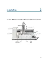
Страница 17: ...2 1 2 This section takes you through the steps for setting up your Quad Z 215 Liquid Handler Installation...

Страница 18: ...ounting screws are shipped in a separate box with the liquid handler s accessories To install the locator plate onto the instrument bed 1 Make sure the locator plate s rinsing station base is at the r...

Страница 19: ...ion This results in an error state during operation If you need to move the liquid handler always reinstall the armlock This safeguards against mechanical damage To remove the armlock 1 Remove the car...

Страница 20: ...m Turn counterclockwise to loosen 2 Partially pull out the bracket Do not remove completely 3 Place the Z arm into the mounting bracket You will need to insert one side of the Z arm into place at a ti...

Страница 21: ...2 Extend the arm to the extreme X and Y direction to ensure that the cable will have enough slack Plug the Z arm control cable into the back topside of the control cabinet The control cable should be...

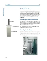
Страница 22: ...ing procedures and diagrams Installing the Probe Guide Inserts Your Quad Z is delivered with 1 5 mm probe guide inserts installed If you ordered custom sized probe guide inserts for more precise XY ac...

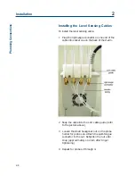
Страница 23: ...lied with the Z arm 3 Pass the other end of each transfer tubing through the open end of an LLD cable casing nearest the right angle connector The tubing should exit the back of the LLD cable casing a...

Страница 24: ...e end of the cable into socket one on the back of the Z arm 2 Snap the cable into the LLD cable guide refer to the picture above 3 Loosen the small hexagonal nut on the probe holder for probe one Atta...

Страница 25: ...plications where the probe is only immersed in a few millimeters of the sample Deep pocket rinse Used for non level sensing applications This type of insert allows for a deeper insertion of the probe...

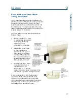
Страница 26: ...se station onto the base follow these steps 1 Align the triangle on the bottom of the rinse station with the base 2 With the rinse station s fittings facing you insert the rinse station into the base...

Страница 27: ...re using refer to the appropriate procedures on the following pages Code 200 Series and Code 500 Series Racks If all your racks are Code 200 series or Code 500 series racks place them directly onto th...

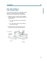
Страница 28: ...series racks on the locator plate 1 Install each Code 200 series rack as described on page 2 11 2 For each Code 20 series or Code 30 series rack place an adapter plate onto the locator plate Fit the...

Страница 29: ...le Injection Module installed follow the steps below 1 Install the locator tray part number 2504627 ordered separately onto the locator plate of the liquid handler For Code 20 series racks the handles...

Страница 30: ...Description 25051094 125 mm Z height adjustment tool Use this tool to adjust the Z arm on the Quad Z 215 Liquid Handler for liquid handling and injection 25051095 175 mm Z height adjustment tool Use t...

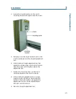
Страница 31: ...inst the locator plate use the other hand to lower the Z arm until it lightly rests on the adjustment tool 7 Tighten the mounting screw on the Z arm mounting bracket so the Z arm is secure 8 While hol...

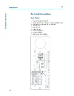
Страница 32: ...Panel 1 Input Output I O ports 2 Gilson Serial Input Output Channel GSIOC port 3 Keypad port not used on the Quad Z 4 RS 232 port 5 Fuse drawer 6 Power switch 7 Power receptacle 8 Unit ID selector 9...

Страница 33: ...or other device Never connect voltages higher than 5V DC to an input When using TTL signals be sure to match GROUND connections Contact outputs The output terminal block has 10 contacts Pins 1 and 2 s...

Страница 34: ...connections be sure to maintain the correct orientation of the connector relative to the port Push the wire all the way in then tighten its corresponding pin screw 4 Reconnect the terminal block conne...

Страница 35: ...ter The liquid handler requires a 25 pin male D connector Refer to the back panel of your computer or its documentation to determine which type of D connector it requires RS 232 cables are available f...

Страница 36: ...mputer GSIOC cable Use the GSIOC cable to link an additional Gilson GSIOC module to the liquid handler and control both devices via a program executed on the computer Connect the female connector loca...

Страница 37: ...iquid handler to Gilson software packages that can issue GSIOC commands to the liquid handler At the factory Gilson set the unit ID to 22 There is no need to change this number unless it is the same a...

Страница 38: ...ace from Gilson control software A setting of 0 indicates the liquid handler is a slave device and the baud rate is being clocked externally Note that other selections are available if the liquid hand...

Страница 39: ...ard the other fuse drawer 2 Locate the accessory package containing the 5 0A T Slo Blo fuse 5 x 20 mm size fuses 3 Install the fuse s into the fuse drawer The fuse drawer for 100 120V accepts one fuse...

Страница 40: ...llation 2 Electrical Connections Power Cord Connection Locate the appropriate power cord for your line voltage Discard the other power cord Use the power cord to connect the liquid handler to an AC po...

Страница 41: ...follows Via a method running on a personal computer You create the method using 735 Sampler Software ordered separately part number 2106773532 If you have not already done so install the 735 Sampler...

Страница 42: ...probe and move the arm When pressed the yellow LED light is turned off In a situation where an emergency stop is required pressing the Stop button immediately stops the liquid handler The Stop button...

Страница 43: ...e what PROM version is installed in your liquid handler you may need to turn the unit off then on again and watch the display for the version number to appear 3 After the liquid handler powers up pres...

Страница 44: ...a an RS 232 cable Refer to Section 2 for correct installation of the RS 232 cable between the liquid handler and the computer The following utility programs may be used with the Quad Z 215 Liquid Hand...

Страница 45: ...ust the default configuration to make sure it is correct for your application The following pages describe how to use 215 Setup Utility to configure the liquid handler This information is also availab...

Страница 46: ...p Utility can communicate with that instrument This tab also lists software version and copyright information for the 215 Setup Utility Unless the Non Volatile RAM has been cleared information about t...

Страница 47: ...5 Liquid Handler uses an external dilutor Blank Front is selected and all options are inactive Syringe Options All options on this tab are inactive for the Quad Z 215 Liquid Handler because it has an...

Страница 48: ...te coordinates if you have a Quad Z 215 Liquid Handler Refer to the following table to select the correct X Y and Z coordinates depending on the kind of probe rinse that will be performed Coordinates...

Страница 49: ...resses false liquid detection while lowering the percentage increases sensitivity for situations where liquid is harder to detect By lowering the probe so it touches the liquid for one of your samples...

Страница 50: ...ssels in the installed racks The X offset and Y offset text boxes display the current offsets stored in the instrument s memory To determine if the probe s need s to be adjusted in the X or Y directio...

Страница 51: ...alled next to the right support use the following coordinates X coordinate 351 1 mm Y coordinate 1 3 mm model 841 X coordinate 475 3 mm Y coordinate 3 8 mm model 889 X coordinate 336 1 mm Y coordinate...

Страница 52: ...Quad Z 215 Liquid Handler because there is only one tower height available The Z arm can be clamped at an adjustable height over the locator plate You can set this height so that the liquid handler is...

Страница 53: ...or the back and left walls of the unit The liquid handler expects to find these walls in the same place each time If it does not you will get an error If this error was caused by an obstruction just c...

Страница 54: ...present a contact closure or TTL type interface The Safety Contact tab allows you to specify which input contact is connected to the safety device and what is the active state of that device The func...

Страница 55: ...range of 0 through 7 where 0 is the dimmest and 7 is the brightest Default setting is 5 Emergency Contact The emergency stop option provides for sending a signal to a peripheral device such as a Gilso...

Страница 56: ...s to be controlled by the Quad Z 215 Liquid Handler The program also identifies the state of input contacts and lets you test the Start and Stop buttons on the liquid handler Before using this softwar...

Страница 57: ...n optimum performance and maximum life from the Quad Z 215 Liquid Handler it is important to keep the instrument well maintained This section contains some general guidelines that will help you to mai...

Страница 58: ...ush the probe housings and rinse stations daily with distilled or deionized water On a weekly basis flush with a 10 solution of bleach or weak detergent Check periodically to ensure that all fittings...

Страница 59: ...using a dry clean cloth Cleaning the Fluid Path Depending on your use of the liquid handler it may be necessary to flush the entire fluid path It s important to clean the fluid path if you won t be u...

Страница 60: ...tion Proteins and peptides Follow this procedure if the fluid path is in contact with proteins and peptides 1 Prime the fluid path using a weak detergent solution 2 Pause the priming sequence 3 After...

Страница 61: ...onized water Prime until the fluid path has been flushed with water 4 Pause the priming sequence 5 Prime the fluid path using a 0 1N NaOH solution Continue to prime until the fluid path has been flush...

Страница 62: ...using the bleach solution until the entire fluid path has come into contact with bleach 3 Pause the priming sequence 4 After 30 minutes resume priming the fluid path using distilled or deionized wate...

Страница 63: ...Mobile 007 grease part number 25494101 included in the 215 Alignment Kit part number 254941 Applicator a cotton swab for example Procedures 1 Turn OFF power to the Quad Z 215 2 Dispense a small bead...

Страница 64: ...r 7 Apply the grease to the visible and accessible areas on the vertical rods and horizontal pitch rods on the Z arm see below 8 Repeatedly and slowly move the probe holders up and down to distribute...

Страница 65: ...tructions below depending on whether you re replacing a probe with one of the same type or one of a different type Installing same type of probe To install a replacement probe of the same type that s...

Страница 66: ...robe holder 2 Grasp the current probe and push it up through the top of the isolation probe holder 3 Remove the current probe guide insert by turning it counterclockwise Then place the new probe guide...

Страница 67: ...49041032 to loosen and remove the 1 4 28 nut and ferrule 2 Unplug the right angle connector for the liquid level sensing cable LLD cable from the socket on the back of the Z arm 3 Detach the LLD cabl...

Страница 68: ...ing to the top of the isolation probe holder using a 1 4 28 nut and ferrule supplied with the tubing Firmly tighten this fitting using the supplied headless nut extender part number 49041032 since it...

Страница 69: ...ate the fuse drawer on the rear panel See page 2 16 if necessary 3 Insert a small screwdriver into the notch next to the fuse drawer 4 Twist the screwdriver to open and remove the fuse drawer The fuse...

Страница 70: ...urrent offsets stored in the instrument s memory To determine if the probe s need s to be adjusted in the X or Y direction select the model of the injection module that is on your Quad Z probably an 8...

Страница 71: ...ndler Transporting the Liquid Handler When moving the liquid handler to another location or when sending it back to the factory do not use the Y arm as a handle Reinstall the armlock see Section 2 and...

Страница 72: ......

Страница 73: ...5 1 5 Troubleshooting...

Страница 74: ...Q command using the GSIOC Utility Program to read the travel range Correct the error in the program controlling the liquid handler 25 X target more than maximum X Send the immediate Q command using th...

Страница 75: ...phases are invalid Run 215SETUP EXE or the 215 Setup Utility program to correct the problem 39 Stop button has been pressed Turn power off then on to the liquid handler 41 GSIOC communication error C...

Страница 76: ...inding tube center Probe s may be bent Straighten or replace the probe Incorrect tray file defined Review and if necessary change the tray file Liquid handler may be misaligned Perform the position al...

Страница 77: ...ectly Check polarity of input Inputs should be a contact closure If not it must be TTL level logic 0 activates Confirm that source supplying input to liquid handler is working Output functions not ope...

Страница 78: ...sure power is turned on Check AC power cord connections Try different AC outlet Check fuse s replace if necessary Check all liquid handler connections and make sure that the unit is plugged in Unit b...

Страница 79: ...only if there is electrical conductivity in your liquid Liquid level detecting will not work with most non polar liquids For intermediate polarity liquids and polar liquids check the sensitivity sett...

Страница 80: ...s you were using when the problem arose list of other devices connected to the liquid handler and a description of those connections list of other electrical connections in the room Warranty repair Un...

Страница 81: ...g proper method of shipment No responsibility is assumed by Gilson for damage caused by improperly packaged instruments Indicate the authorization on the carton and on the packing slip Always insure f...

Страница 82: ......

Страница 83: ...steel Dimensions 269 x 1 8 x 1 4 mm ID Requires probe guide insert part number 25064473 for precise XY accuracy 25073645 Non septum piercing probe beveled tip capacitive level sensing stainless steel...

Страница 84: ...064471 Probe guide insert for 1 3 mm outer diameter probes 25064475 Probe guide insert for 2 7 mm outer diameter probes Transfer Tubing and Waste Bottle 250531734 1 1 mL 1 6 mm 1 16 OD transfer tubing...

Страница 85: ...inse station base attaches directly to 215 locator plate 23077333 Y connector to connect two rinse stations to one waste bottle Rack Accessories For part numbers for available racks refer to Appendix...

Страница 86: ...male to 25 pin male 36083123 Serial cable adapter 9 pin female to 25 pin male 638308512 Terminal block connector 8 pin 638310512 Terminal block connector 10 pin 709910206 2 conductor interconnect wire...

Страница 87: ...Z 215 Liquid Handler can be configured with a variety of rack types and sizes The following pages describe the racks that can be purchased for use on the liquid handler Refer to Section 2 for rack ins...

Страница 88: ...13 x 100 mm tubes 9 mL Part number 150422 Required accessories adapter plate part number 2504621 Code 23 rack For 44 vessels Material polypropylene Vessels and maximum capacity 17 x 55 mm vials 6 8 m...

Страница 89: ...For 60 vessels Material aluminum Vessels and maximum capacity 12 x 32 mm vials 2 mL Part number 2704430 Required accessories adapter plate part number 2504621 and thermostating cuvette part number 270...

Страница 90: ...ber 2759550 and 832 Temperature Regulator part number 2759502 Code 33 rack Thermostated rack for 14 scintillation vials Material aluminum Vessels and maximum capacity 28 x 60 mm 20 mL Part number 2704...

Страница 91: ...two microplates two Eppendorf vials and two 13 x 100 mm tubes with microplate covers Material aluminum Vessels and maximum capacity 96 well microplates Eppendorf vials 1 5 mL 13 x 100 mm tubes 9 mL P...

Страница 92: ...two 13 x 100 mm tubes Material aluminum Vessels and maximum capacity 96 deep well microplates Eppendorf vials 1 5 mL 13 x 100 mm tubes 9 mL Part number 2504605 Code 205H rack For two deep well microp...

Страница 93: ...ode 207 rack For 75 vessels Material aluminum Vessels and maximum capacity 16 x 100 mm 12 mL Part number 2504607 Code 208 rack For 70 vessels Material aluminum Vessels and maximum capacity 18 x 150 mm...

Страница 94: ...48 x 113 mm 125 mL Part number 2504611 Code 212 rack For 96 vessels Material aluminum Vessels and maximum capacity 48 13 x 100 mm 9 mL 48 13 x 75 mm 7 mL Part number 2504612 Note Place the shorter tub...

Страница 95: ...uminum Vessels and maximum capacity 60 15 x 45 mm 4 mL Part number 2504616 Code 217 rack For 96 tubes Material aluminum Vessels and maximum capacity 96 10 x 75 mm culture tubes 3 5 mL Part number 2504...

Страница 96: ...622 Code 228 rack For four reagent bottles Material aluminum Vessels and maximum capacity 4 500 or 700 mL Part number 2504628 Code 505 rack For 10 standard or deep well microplates Material aluminum P...

Страница 97: ...well microplates Part number 25146331 Note Order Peltier Controller part number 2515331 and junction box part number 2505332 separately Code 542 Peltier rack For 10 shallow flat bottom 96 well micropl...

Страница 98: ...oller part number 2515850 separately Code 853 Peltier rack For 96 12x32 mm 2 ml flat bottom vials Material aluminum Part number 2514853 Note Order Programmable Peltier Controller part number 2515850 s...

Страница 99: ...ue number which must be known to the device and to the computer The default ID code of the Quad Z 215 is 22 To control the Quad Z 215 Liquid Handler via the GSIOC interface you will need the following...

Страница 100: ...ust be entered in the proper upper or lower case format If a buffered command requires additional information you ll see italicized text next to the command The description of the command identifies w...

Страница 101: ...B Sets test mode depending on value assigned to n 1 XYZ test 9 Reset NV RAM and initialize to defaults 9 I Reads contact input event FIFO Returns Xtttttt where X State of the four contact inputs 1 fo...

Страница 102: ...ddress 0 to 7 of user defined character ss ss Characters in hexadecimal ASCII code for rows 1 through 7 See example below For example the following command sets the pattern shown below to user defined...

Страница 103: ...ted 0 if open kk Status of front panel Start and Stop buttons 1 if button has been pressed 0 if it hasn t been pressed Value of kk is cleared after reading J I Reads status of output contacts Returns...

Страница 104: ...X Y Z motor status and dilutor status Returns xyzp For each status you ll see U for unpowered P for powered R for running or E for error Note Because the Quad Z uses an external dilutor the dilutor st...

Страница 105: ...The default speed is 125000 m s O I Reads each probe speed value in m s Returns a b c d where a speed of probe A b speed of probe B c speed of probe C d speed of probe D P I Reads X and Y encoder posi...

Страница 106: ...B Sends a synchronized buffered command mm that will be executed when the instrument is quiescent Sending a command can overwrite unexecuted existing commands If you send this command without indicat...

Страница 107: ...mm where n is a value from 90 to 180 w I Reads the probe width in integral units of 0 1 mm x I Indicates X motor status Returns one of the following U for unpowered P for powered R for running or E f...

Страница 108: ...nd y coordinates Xdx y B Moves probe D to target x and y coordinates Yyyyy B Sets new Y position yyyy is the new position in integral units of 0 1 mm z I Indicates Z motor status Returns one of the fo...

Страница 109: ...chniques you ll be able to maximize accuracy and precision and minimize carryover with your Quad Z 215 Liquid Handler Accuracy and precision of pipetting are dependent on the specifications of the pum...

Страница 110: ...miting immersion below the liquid surface Cleansing the probe tip with a flowing rinse removes contaminants from the external surfaces of the probe Dispensing liquid through the probe into the rinsing...

Страница 111: ...ts for sample purity and precision You can aspirate an air gap into the probe tip to separate different fluids passing through the tubing to reduce mixing You can aspirate an amount in excess of the r...

Страница 112: ...owever in order to save time the operator wishes to make a single 1 mL aspiration from the reagent reservoir and then make multiple dispenses If the 8 step procedure was not used the last aliquot of t...

Отзывы: