Gilson Company, Inc.
Gilson Binder Ignition System: HM-378
Page 16
Problem #2: Controller Display Lights Up Normally;
Some or All Heating Elements Do Not Fire
Probable Causes:
1. Worn or burned-out elements.
2. Defective controller board.
3. Defective relay(s).
4. Disconnected wire in switch box.
First check the controller board with a voltmeter. Make
sure the furnace is unplugged. Remove the four screws
holding the controller board faceplate to the switch box.
Lift the faceplate out of the box and let the board hang
on the box with the back of the board facing you. Plug
the furnace back in. Program the controller to fire the
furnace at full power.
Put the voltmeter in
DC mode. Touch the probes to the
red and black wire connectors. If voltage is present (ap-
proximately 12 VDC) current is going to the relays from
the board, so the board is okay. If there is no voltage at
the red and black wire connectors, replace the board.
If the controller board checks out okay,
disconnect and
lock out the power supply, and remove the switch box.
Look for loose or disconnected board to relay, relay to
element, and cord set to relay wires.
If you still haven’t found the problem, check the elements
with an ohmmeter.
Be sure the power supply is still
disconnected. Touch the ohmmeter leads to the two ele-
ment connectors of each element. No needle movement
indicates a broken (burned-out) element.
If the element you are testing has two or more element
lead wires attached to the same element connector, you
must temporarily disconnect those wires. Hold the element
connector with pliers as you remove the brass screw. Be
gentle to avoid breaking the element. Elements are brittle
after being fired. DO NOT disturb the stainless steel screw
holding the element, only the one holding the lead wires.
Reconnect the wires securely after testing the element.
If the elements and wiring check out okay, the problem
is most likely a relay.
Problem #3: FAIL or TC2 Message
Probable Causes:
1. Defective thermocouple.
2. Disconnected thermocouple lead wires.
3. Reversed thermocouple lead wires.
4. Defective board.
The controller displays
TC2 when the thermocouple (tem-
perature sensor) in the firing chamber burns out and
FAIL
when the thermocouple in the Afterburner chamber burns
out.
Disconnect and lock out power supply. Remove
the four screws holding the controller faceplate to the
switch box. Lift the faceplate out of the box. Look at the
back of the board. You will see two wires, each with a red
and yellow conductor, near the bottom of the board. If one
of these wires is disconnected or loose, lift the locking
bar, reseat the wires, and press the locking bar back into
place. Be sure the color of the wire matches the color of
the connector. The controller should work now.
If the wires are attached securely to their connectors,
remove one pair of red and yellow wires from the con-
nector. Touch ohmmeter probes to the red and yellow
wires. If you get continuity (0 ohms), place the wires back
into the connector being sure to match the wire color to
the connector color. Remove the other pair of red and
yellow wires from the connector. If you get continuity (0
ohms), replace the board. If there is no movement of the
ohmmeter needle (infinity, or no continuity) with either
thermocouple, you have a burned out thermocouple or a
disconnected thermocouple wire.
Problem #4: Controller Displays ETH (Electronics Too Hot)
The circuit board temperature is above 185°F/85°C. Open
windows and use a fan to circulate the air in the room before
firing the furnace. If you have more than one furnace in
the room, place them farther apart. Never allow the firing
room temperature to exceed 110°F/43°C. (Measure room
temperature three feet away from the furnace.)
Problem #5: Controller displays PLOG
A PLOG error code indicates that the controller failed a
self-diagnostic test. The controller will not operate while a
PLOG message is displayed. Clear the PLOG error code
by pressing <ENTER>. If that doesn’t work, turn off the
power to the furnace for 10 seconds. If the PLOG mes-
sage remains after 3 Resets and after you have turned
off power for 10 seconds, the controller is defective.
Содержание HM-378
Страница 18: ...Gilson Company Inc Gilson Binder Ignition System HM 378 Page 18 Figure 1 Parts Accessories Diagram ...
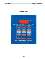
Страница 19: ...Gilson Company Inc Gilson Binder Ignition System HM 378 Page 19 Control Panel Figure 2 ...
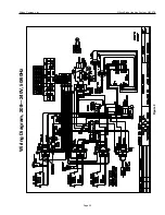
Страница 20: ...Gilson Company Inc Gilson Binder Ignition System HM 378 Page 20 Figure 3 Wiring Diagram 208 240V 50 60Hz ...

