Gilson Company, Inc.
Gilson Binder Ignition System: HM-378
Page 4
See Section 1.0 for instructions on releasing the door lock
to open the door and remove packing material.
Carefully inspect the furnace as soon as it arrives and
check for all enclosures. If the furnace is damaged or if
parts are missing, contact Gilson Customer Service im-
mediately at 800-444-1508 or 740-548-7298 for instruc-
tions. Save all packing materials for inspection by the
freight claims adjuster if damage is reported.
The following accessory items are supplied with the
furnace:
• 2
Sets of Sample Basket, Screen, and Cover
(Extra sets available as HMA-69)
• 1
Loading/Unloading Fork
• 1
Replaceable Filter
(Order extra as HMA-812, box of 12)
• 1
Filter Holder
• 2
Two-Piece Hearth Plate
• 1
Cooling Tray
• 1
NEMA 6-50 Cord/Plug Set
The furnace is supplied with an electrical cord for
230V/60Hz single phase operation. For connection to
other voltages, 50Hz, or three phase by an electrician,
see the wiring diagram packed on top of the furnace and
also Figures 3 & 4 of this manual.
The blower assembly is shipped installed on the top of
the furnace with exhaust vent connection to the rear. It
can also be installed on the rear with vent connection to
the top if desired.
WARNING!
The blower assembly of this furnace must be con-
nected to an exhaust vent prior to use. Failure to do
so will result in combustion product fume emissions
from the furnace into the laboratory environment.
Fumes may cause eye or lung irritation or more se-
vere injury, depending on compounds in the binder
being burned.
While other types of exhaust venting may be used, a vent
kit as used for a home clothes dryer is suitable. Such kits
are obtainable locally in hardware or appliance stores or
can be purchased from Gilson as model HMA-814.
The two 10 x 20in Hearth Plates are to be placed on the
floor of the main chamber. They are designed as a wear-
ing surface to prevent erosion of the firebrick.
1. Place the furnace in a well ventilated, covered and
protected area.
DO NOT store gasoline, paint or other
flammable liquids in that room.
2. Provide a minimum of 12in (305mm) clearance be-
tween the furnace and the closest combustible wall,
or 6in (152mm) to masonry walls.
3. Keep the furnace away from curtains or other combus-
tible materials.
DO NOT place combustible materials
on or near the furnace.
4. Position the furnace on a level, fireproof surface. The
Model HMA-810 Furnace Support Stand accessory
has a convenient working height. If the accessory
stand is not used, a metal table is recommended.
5. Keep the power supply cord away from the side of
the furnace. The furnace case is hot during firing and
touching could damage the cord set.
The heating elements of the furnace may have become
dislodged during shipping. Before firing the furnace for
the first time, please make sure the elements are seated
in their grooves.
WARNING!
ALWAYS unplug furnace and lock out electrical
supply before touching an element with anything.
Press the elements into their grooves by running a blunt
object such as a wooden tongue depressor or plastic
comb completely around each groove. The element must
fit all the way back into each corner and must NOT bulge
outside the groove. The element will not seat in the curved
portions of the groove, but must be seated in the straight
grooves and corners.
NOTE: Before the furnace is fired, there is little
danger of breaking the elements. After firing,
however, the elements must be reheated using a
special procedure if they bulge out of the groove.
See Section 10.2.1, "Reseating the Elements" for
instructions.
4.0 UNPACKING & SETTING UP FURNACE
5.0 WHERE TO LOCATE FURNACE
6.0 SEATING THE ELEMENTS
Содержание HM-378
Страница 18: ...Gilson Company Inc Gilson Binder Ignition System HM 378 Page 18 Figure 1 Parts Accessories Diagram ...
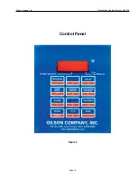
Страница 19: ...Gilson Company Inc Gilson Binder Ignition System HM 378 Page 19 Control Panel Figure 2 ...
Страница 20: ...Gilson Company Inc Gilson Binder Ignition System HM 378 Page 20 Figure 3 Wiring Diagram 208 240V 50 60Hz ...


