Gilson Company, Inc.
Gilson Binder Ignition System: HM-378
Page 15
WARNING!
ALWAYS disconnect and lockout the electrical
supply to the furnace prior to maintenance or repair.
Diagnostic and repair procedures performed in or
around high-voltage circuits should be conducted
only by a qualified electrician.
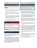
Controller Self Test
The Controller will enter a self test mode if the <4> key is
pressed while power is applied to the furnace. This mode
will sequentially test each of the inputs and outputs to
the controller card. Upon entering the self-test mode, the
display will show
FAN and the exhaust fan will be turned
on. No other controller outputs will be turned on except the
fan. This situation will remain until the operator presses
<ENTER> or removes power from the furnace.
Upon pressing <ENTER> the display will show
LOCK
and the fan will be turned off. At this point the output
controlling the door lock will be turned on and the door
latch mechanism can be tested. This situation will remain
until the operator presses <ENTER> or removes power
from the furnace.
Upon pressing <ENTER> the display will show
ALAR and
the alarm output will be turned on. Since this function is
reserved for future use, no visual effect will be noticed.
This situation will remain until the operator presses <EN-
TER> or removes power from the furnace.
Upon pressing <ENTER> the display will alternately display
MAIN and the main chamber temperature. The Lower
red pilot light on the front panel of the switch box will also
be on. If the pilot light is not on, be sure the door is in the
closed position and latched. This activates a switch that
applies power to the main chamber elements only when
the door is closed. Leave the furnace in this condition for
several minutes and note the readings for the main cham-
ber temperature. They should be increasing indicating
the main chamber is getting warmer. If the readings are
decreasing, the thermocouple leads are connected to the
controller card with the wrong polarity. Do not leave the
furnace unattended in this situation, as there is no upper
limit on the main chamber temperature. If left unattended
the elements will burnout due to thermal runaway. The fur-
nace will remain in this situation until the operator presses
<ENTER> or removes power from the furnace.
Upon pressing <ENTER> the display will alternately show
AFT and the temperature in the Afterburner chamber.
Leave the furnace in this condition for several minutes
and note the readings for the Afterburner chamber
temperature. They should be increasing indicating the
Afterburner chamber is getting warmer. If the readings
are decreasing, the thermocouple leads are connected
to the controller card with the wrong polarity. Do not leave
the furnace unattended in this situation as there is no
upper limit on the after burner chamber temperature. If
left unattended the elements will burnout due to thermal
runaway. The furnace will remain in this situation until
the operator presses <ENTER> or removes power from
the furnace.
Upon pressing <ENTER> the display will alternately
display
IdLE and the temperature of the main chamber.
At this time the furnace is ready to run and is out of the
self test mode.
Problem #1: Controller Display does Not Turn On
Probable Causes:
1. Tripped circuit breaker or blown fuse; furnace unplugged.
2. Blown furnace switch box fuse.
3. Defective transformer.
4. Defective controller board.
5. Disconnected wire in switch box.
Check circuit breakers or fuses for the wall outlet. Then,
remove the furnace fuse and check it by placing the leads
of an ohmmeter on the ends of the fuse. If the ohmmeter
reading is 0 ohms, the fuse is okay. If the reading is infinity
or no needle movement, the fuse is bad. Replace a bad
fuse with a SS2-250mA, 250VAC fuse.
Next, check the controller board with a voltmeter. Make
sure the furnace is unplugged. Remove the four screws
holding the controller board faceplate to the switch box.
Lift faceplate out of box and let the board hang on the box
with the back of the board facing you. Plug the furnace
back in. Touch the voltmeter probes, in AV Volt mode, to
connectors with the orange and white wires. Make sure the
voltmeter is in the AC mode when placing the probes on
these connectors. If you find voltage (approximately 20V
AC) present, that means current is reaching the board from
the transformer, so the board is probably defective.
If there is no voltage, the transformer is probably defec-
tive. But before replacing the transformer,
disconnect
and lockout the power supply. Remove the switch box
and look for both a disconnected wire between the cord
set and transformer and between the transformer and
the controller board.
11.0 THE TEMPERATURE CONTROLLER - TROUBLESHOOTING
Содержание HM-378
Страница 18: ...Gilson Company Inc Gilson Binder Ignition System HM 378 Page 18 Figure 1 Parts Accessories Diagram ...
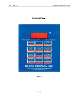
Страница 19: ...Gilson Company Inc Gilson Binder Ignition System HM 378 Page 19 Control Panel Figure 2 ...
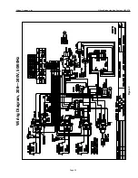
Страница 20: ...Gilson Company Inc Gilson Binder Ignition System HM 378 Page 20 Figure 3 Wiring Diagram 208 240V 50 60Hz ...


