
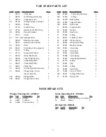


ITEM PART DESCRIPTION
QTY.
1
08377
Crankcase
1
2
08378
Oil Fill Plug with Gasket
1
3
06479
Crankcase cover
1
3A
07186
Oil Sight Glass w/ Gasket
1
4
08380
O-Ring
1
5
07109
Oil Drain Plug
1
5A
07182
Gasket for Oil Drain Plug
1
5B
08092
Plug with Gasket
1
6
01010
Screw
4
6A
01011-0400
Spring Washer
4
7
05290
Bearing Cover Open
1
8
05291
Bearing Cover Closed
1
8A
05292
Shim
3
8B
05293
Shim (May not be present)
1
9
01016
O-Ring
2
10
07114
Screw with Washer
8
11
07459
Radial Shaft Seal
1
12
05350
Taper Roller Bearing
2
13
08475
Crankshaft (P435)
1
13
08482
Crankshaft (P455)
1
14
08091
Fitting Key
1
15
08390
Connecting Rod Assembly
3
16
05484
Plunger Assy.,18mm
(Items 16A-16H)
3
16A
05352
Plunger Base
3
16B
08397
Plunger Pipe, 18mm
3
ITEM PART DESCRIPTION
QTY.
16D
08399
Tensioning Screwing
3
16E
07023
O-Ring
3
16F
07203
Backup Ring
3
16G
07258
Copper Washer
3
16H
06431
Oil Scraper
3
17
06790
Crosshead Pin
3
19
05444
Oil Seal
3
20
05534
Seal Case
3
21
07266
O-Ring
3
23
08477
V-Sleeve, 18mm
6
24
07929
Pressure Ring
3
25
08402
Weep Return Ring
3
26
05574
Manifold - Brass
1
27A
05543
Valve Assy.
6
27
05541
Valve Seat
6
28
05542
Valve Plate
6
29
07906
Valve Spring
6
30
07907
Valve Spring Retainer
6
31
07770
O-Ring
6
32
05544
Plug
6
33
05545
O-Ring
6
34
08484
Cap Screw
8
36
13434
Plug, 1/2" BSP
1
36A
06272
O-Ring (P455 Only)
1
37
07703
Plug, G 3/4"
1
P455B REPAIR KITS
Valve Assembly Kit - # 09644
Item
Part
#Description
Qty
27A
05543
Valve Assembly, Complete 6
33
05545
O-Ring
6
Oil Seal Kit - #09641
Item
Part #
Description
Qty
19
05444
Oil Seal
3
Plunger Packing Kit - # 09643
Item
Part
#Description
Qty
21
07266
O-Ring
3
23
08477
V-Sleeve
6
24
07929
Pressure Ring
3
P455 SPARE PARTS LIST
5
Содержание P435B
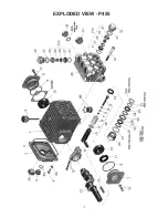
Страница 4: ...EXPLODED VIEW P455 4 ...
Страница 10: ...10 Keyway 8x7x45mm ...
Страница 11: ...NOTES 11 ...


