2
INSTALLATION INSTRUCTIONS
When the pump is in operation, the open shaft
end must be covered up by a shaft protector
(21). For direct drive operations, the driven
shaft side and coupling must have a guard
over the connected area.
Pressure in discharge line and in pump must
be at zero before any maintenance to the
pump takes place. Close the fluid supply to
the inlet port(s). Disconnect fuses to ensure
that the driving motor does not accidentally get
switched on. Make sure that all parts on the
pressure side of the unit are vented and re-
filled, with pressure at zero, before starting the
pump.
In order to prevent air, or air/water mixture
being absorbed and to prevent cavitation oc-
curring, the pump-npshr, positive suction head
and water temperature must be kept under
control.
Required NPSH refers to water: Specific
weight 0.0624 lb/ft
3
(1kg/dm
3
), viscosity 1°E at
maximum permissible revolutions.
Cavitation and/or compression of gases
lead to uncontrollable pressure kicks which
can ruin pump and unit parts and also be
dangerous to the operator or anyone stand-
ing nearby.
Giant pumps are suitable for pumping clean
water and other non-aggressive or abrasive
media with a specific weight similar to water.
Before pumping other liquids - especially
inflammable, explosive and toxic media -
the pump manufacturer must under all cir-
cumstances be consulted with regard to the
resistance of the pump material. It is the re-
sponsibility of the equipment manufacturer
and/or operator to ensure that all pertinent
safety regulations are adhered to.
Operation and Maintenance
Check oil level prior to starting and ensure
trouble free water supply.
IMPORTANT!
If there is a
danger of frost,
the water in the pump and in the pump fittings
(particularly the unloader valve) must be emp-
tied. The second discharge port can also be
used and the pump run “dry” for 1-2 minutes
for this purpose.
Oil: Use only 118 fluid ounces (3.5 L) of SAE
90 Industrial gear lube oil. (Giant’s p/n 01154)
Initial change after 50 operating hours and
then every 1000 operating hours, or after one
year if used less.
Caution!
When operating in damp places or
with high temperature fluctuations, conden
-
sate (frothy oil) might occur in the gear box.
In this situation, change the oil immediately.
Keep NPSH under control.
Maximum input pressure is 145 PSI (10 bar),
the maximun suction head is -4.35 PSI (-0.3
bar). Make sure that suction pulsation is suf-
ficiently dampened. Water column resonance
must be avoided.
Safety Rules
Pump operation without safety valve as well
as any excess in temperature or speed limits
automatically voids the warranty. The safety
valve must be regulated in accordance with
the guidelines for liquid spraying units so that
the admissible operating pressure can not be
exceeded by more than 10%.
NOTE: Contact Giant Industries for Service School Information. Phone: (419)-531-4600
Содержание LP200-SS
Страница 4: ...4 Exploded View LP200 SS...
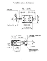
Страница 11: ...11 Pump Dimensions Inches mm...


