background image

8

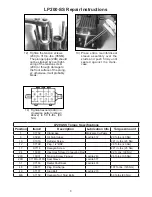
12)  Tighten the tension screws 

(29C) to 310 in.-lbs. (35NM).

The plunger pipe (29B) should 

not be strained by over tight-

ening of the tension screw 

(29C) or through damage to 

the front surface of the plung-

er; otherwise, it will probably 

break.  

13)  Place  entire  manifold/seal 

sleeve assembly over the 

studs and push firmly until 

seated against the crank-

case. 


LP200-SS Repair Instructions

14)  Tighten hex nuts (49A) in a 

crosswise pattern (shown 

above) to 59 ft.-lbs. (80 

Nm).


LP200-SS Torque Specifications

Position

Item #

Description

Lubrication Info

Torque Amount

1

07759

Crankcase

Molycote Cu-Paste

6

05943

Oil Sight Glass

Loctite 572

29 ft.-lbs. (40 Nm)

10

01010

Cylinder Screw

221 in.-lbs. (25 Nm)

12

07109

Plug, 1/2” BSP

29 ft.-lbs. (40 Nm)

17

07114

Hexagon Screw

221 in.-lbs. (25 Nm)

24

13340

Inner Hex Screw, Connecting Rod

22 ft..-lbs. (30 Nm)

29C

13031

Tension Screw, Plunger

Loctite 243

26 ft.-lbs. (35 Nm)

29D

07161A-0100

Seal Sleeve

Loctite 577

31

07133

Radial Shaft Seal

Loctite 403

48

06077

Plug, Discharge

107 ft.-lbs. (145 Nm)

49

07157

Stud Bolt

Loctite 270

49A

07158

Hexagon Nut, Stud Bolts

59 ft.-lbs (80 Nm)

Содержание LP200-SS

Страница 1: ...e 5 Repair Instructions pages 6 9 Torque Specifications page 9 Pump Mounting Selection Guide page 9 Trouble Shooting page 10 Maintenance Spare Parts List page 10 Dimensions page 11 Warranty Informatio...

Страница 2: ...l cir cumstances be consulted with regard to the resistance of the pump material It is the re sponsibility of the equipment manufacturer and or operator to ensure that all pertinent safety regulations...

Страница 3: ...fied when selecting an electric motor as the power source To compute specific pump horsepower requirements use the following formula HP GPM X PSI 1440 PULLEY INFORMATION Pulley selection and pump spee...

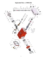
Страница 4: ...4 Exploded View LP200 SS...

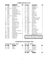
Страница 5: ...IPTION QTY 30 07779 Drip Shield 3 31 07133 Radial Shaft Seal 3 35 13196 Seal Sleeve 3 36 13228 Leakage Seal 3 37 07170 Seal Case 3 38 07140 O Ring 3 38A 12055 O Ring 3 39 13197 Pressure Ring 3 40 1311...

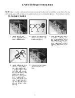
Страница 6: ...Take out discharge valve assemblies 46 by pull ing them upwards out of the valve casing 43 with a snap ring tongs or any other pull off device Then remove inlet valves in the same way 4 Loosen valve...

Страница 7: ...rface of plunger 25 thoroughly Apply a thin coat of Loctite to the tension screw threads 29C Note Care must be taken that no glue gets between the plunger pipe 29B and the centering sleeve 29A Add new...

Страница 8: ...to 59 ft lbs 80 Nm LP200 SS Torque Specifications Position Item Description Lubrication Info Torque Amount 1 07759 Crankcase Molycote Cu Paste 6 05943 Oil Sight Glass Loctite 572 29 ft lbs 40 Nm 10 01...

Страница 9: ...aring ring until the outer edge lines up with the outer edge of the bearing hole Remove bearing cover 14 together with radial shaft seal 15 and o ring 16 Fit crank shaft 22 through bearing hole on the...

Страница 10: ...riction Check system for stoppage air Pressure Drop leaks correctly sized inlet plumbing to pump Accumulator pressure Recharge Replace accumulator Unloader Check for proper operation Cavitation Check...

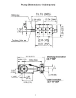
Страница 11: ...11 Pump Dimensions Inches mm...

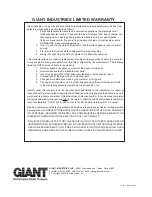
Страница 12: ...tear to standard wear parts 3 Use of repair parts other than those manufactured or authorized by Giant 4 Improper use of the product as a component part 5 Changes or modifications made by the customer...

Отзывы: