background image

Slimdrive SL NT/SL NT-FR

12

Installation

Installation

X

X

Secure workplace against unauthorised entry.

X

X

Always perform work with a second technician.

X

X

Use a stepladder or stepstool.

X

X

Keep inside area of running rail clean.

6.1  Preparations on site

Check the on-site preparations to ensure proper installation:


à

Type and loading capacity of the façade construction or base construction 


à

Evenness of the installation surface


à

Evenness of the finished flooring


à

Requirements of the cable plan

6.2  Installation

6.2.1  Mounting the drive (Part 1)

X

X

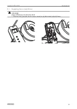
Remove the cover and the pre-assembled module bearer.

InsertXintermediateXplates


1

X

X

Insert the intermediate plates (1) onto the rear of the running rail.


à

Upper row of drill holes for wall mounting


à

Lower row of drill holes for the clip of the intermediate plate

Mounting can also be carried out conversely depending on the building structure (dead bolt design). However, 

use the upper row of drill holes for fixing if possible.

Содержание SL NT

Страница 1: ...1 Slimdrive SL NT SL NT FR GB Installation instructions ...

Страница 2: ...act to the locking device optional 8 5 6 Connecting the cable to the left hand module bearer 8 5 7 Fitting the right hand module bearer 9 5 8 Connecting the cable to the right hand module bearer 9 5 9 Pre positioning the pre mounted module bearer left and right 10 5 10 Pre mounting the roller carriage on the door leaf 10 6 Installation 12 6 1 Preparations on site 12 6 2 Installation 12 6 3 Commiss...

Страница 3: ...echnical notes are emphasised in order to illustrate the correct operation Symbol Meaning means important note Information on avoiding material damage understanding a concept or optimising the processes means additional information X X Symbol for an action Here you have to do something Observe the sequence if there are several action steps 2 Product liability In accordance with the liability of ma...

Страница 4: ...d maintenance work à à The connection to the power supply must be made by a professional electrician Perform the power connec tion and equipment earth conductor test in accordance with VDE 0100 Part 610 à à Use a customer accessible 10 A overload cut out as the line side disconnecting device à à Protect the display programme switch against unauthorised access à à The detection field of the movemen...

Страница 5: ...bles etc can be drawn in by rotating parts à à Danger of injury through unsecured crushing impact drawing in or shearing spots à à Danger of injury by broken glass à à Danger of injury due to sharp edges in the drive à à Danger of injury during installation through freely moving parts 3 4 Inspection of the installed system Measures for security and prevention of pinching impact shearing or drawing...

Страница 6: ... to change Only use the most recent version 4 2 Tool Tool Size Tape measure Marking pen Torque spanner Allen key 2 mm 2 5 mm 3 mm 4 mm 5 mm 6 mm Open ended spanner 8 mm 10 mm 13 mm 15 mm Ring spanner 8 mm 10 mm Screwdriver set Slotted up to 6 mm cross slot PH2 and PZ2 Torx bit T x 20 bit insert length at least 110 mm Pin punch 4 mm Side cutting pliers Crimping pliers for cables Wire stripper Multi...

Страница 7: ...over to the required length 5 2 Fitting the brush X X Cut the brush 1 to the required length and insert into the running rail 2 5 3 Fitting the side plates X X Screw the sheet metal part 2 for securing the cover in the left hand and right hand side panels 3 X X Fit the side panels on the running rail 1 X X Place the stop buffers 4 on the far left and right of the running rail X X Tighten the setsc...

Страница 8: ...alarm contact switch 3 on the feedback switch 4 X X Fix both switches in place on the locking mechanism using M2 3 x 18 2 screws and spring washers X X Connect cable X X Shorten the switching flag of the alarm contact switch 5 6 Connecting the cable to the left hand module bearer X X Lay cable 2 to the toothed belt locking optional 1 cut to size if necessary strip and attach the insulated wire end...

Страница 9: ...g 5 8 Connecting the cable to the right hand module bearer 1 2 1 2 3 Slimdrive SL NT Slimdrive SL NT FR Slimdrive SL NT X X Lay rotary transducer cable 1 and motor connection cable 2 to the control unit X X Insert plug into the control unit Slimdrive SL NT FR X X Lay rotary transducer cable 1 motor connection cable 2 and motor connection cable of the second motor 3 to control unit X X Insert plug ...

Страница 10: ...pply the stickers see the drive drawing à à Information plate enter the date of manufacture supplement digits of Classes 5 and 7 à à TÜV sticker à à Ü symbol for Slimdrive SL NT FR 5 10 Pre mounting the roller carriage on the door leaf For 1 leaf systems X X Slide the clamping plate 1 into the connect ing profile X X Slide the roller carriage 2 4 into the connecting profile 3 X X Secure both rolle...

Страница 11: ...sing setscrews 5 The angled part 8 of the connection profile must be facing the main closing edge X X Mount the long driver 7 to the roller carriage 4 using 2 screws 1 and 2 leaf systems X X Mount the continuous roller carriage on the door leaves with the supporting brackets 8 X X Check whether the thread lies flush with the fixing holes X X If necessary loosen the supporting brackets on the door ...

Страница 12: ...à à Evenness of the installation surface à à Evenness of the finished flooring à à Requirements of the cable plan 6 2 Installation 6 2 1 Mounting the drive Part 1 X X Remove the cover and the pre assembled module bearer Insert intermediate plates 1 X X Insert the intermediate plates 1 onto the rear of the running rail à à Upper row of drill holes for wall mounting à à Lower row of drill holes for ...

Страница 13: ...ding to local conditions see installation diagram X X Install the floor guide 6 2 2 Fitting the door leaf WARNING Danger of injury by broken glass X X Always mount the door leaf together with another person WARNING Danger of crushing The door leaves are still unsecured and slide easily X X Make sure that the door leaves are not moved accidentally or by unauthorised persons X X Remove the roller ca...

Страница 14: ...4 Installation Fitting the roller carriage into the running rail X X Insert roller carriage 2 into the running rail 1 as shown below X X Insert the mounting aid 3 as shown below to secure the roller carriage in the running rail ...

Страница 15: ... door leaf and screwing it in place X X Move the roller carriage 1 into the door opening 4 X X Suspend the door leaf 3 on the height adjustment screws 6 X X Screw the door leaf in place using screws 7 Do not tighten screws yet X X Move the door leaf 3 to the side using the floor guide 5 X X Suspend the other door leaf 2 in the same way ...

Страница 16: ...crews for height adjustment 1 X X Use the setting screw 2 ring spanner size 8 to adjust the height of the door leaves 2 leaf adjust the height of both door leaves X X Tighten the screws 1 and 3 X X Remove the mounting aid X X Move the door leaf into the open position X X Loosen the hexagon socket screws 4 of the stop buffer X X Push the stop buffer on the roller carriages X X Tighten the hexagon s...

Страница 17: ... the motor X X Position the left module bearer 1 in such a way that it does not collide with the locking mechanism or the return pulley X X Screw the pre assembled module bearer left 1 and right 3 to the running rail 2 Tightening torques see drive diagram 6 2 6 Mounting the toothed belt X X Thread the toothed belt on the motor pulley and return pulley shorten if necessary X X Insert toothed belt e...

Страница 18: ...the screw 1 X X Push the screwdriver into the gap and turn it until the toothed belt is tensioned X X Tighten the 2 screws 2 6 2 8 Setting the closing position for 2 leaf systems X X Push the door leaf to the closed position X X Fit second belt locks do not tighten screws 2 yet X X Use the long holes 1 to finely adjust the position in the direction of displacement X X Tighten the screws 2 when the...

Страница 19: ...f necessary strip and attach the insulated wire end ferrules X X Connect the cable to the toothed belt locking optional see chapter 5 4 see wiring diagram X X Place cover 3 on control unit and lock in place The retention force of the cover can be increased by slightly bending the cover 6 2 11 Mounting the safety equipment X X Fit safety and actuation equipment X X Route cables properly in cable du...

Страница 20: ...arer on the left see figure à à at the end of the running rail to earth the cover 6 2 15 Positioning the toothed belt locking optional 1 X X Close the door leaves X X Loosen the screws 1 at the toothed belt locking optional X X Align the locking device to the toothed belt X X Tighten screws 1 X X Lightly lubricate sliding surfaces The driver must not come into contact with the toothed belt locking...

Страница 21: ...ectrician X X Perform the power connection and equipment earth conductor test in accordance with VDE 0100 Part 610 X X Attach the battery plug 1 at the control unit During maintenance work the battery must be disconnected from the control unit X X Check whether the battery cable is long enough attach extension cable if necessary X X Connect drive to 230 V mains 230 VAC 10 50 60 Hz and switch on th...

Страница 22: ...r suspension piece 1 each into the upper and lower screw duct of the cover 2 X X Use 2 screws to secure the cover suspension piece 1 in the end section of the cover Installing the cover earthing 3 X X Knock the locating pin of the cover earthing 3 on the side of the earthing see chapter 6 2 14 approx 30 mm into the upper screw duct ...

Страница 23: ...afety rope 3 at the suspension piece 2 of the side panels X X Mount the earthing wire of the cover earthing onto the tab connector of the earthing piece see chapter 6 2 14 X X Slide the hood onto the side panels until it latches in and ensure that it is also seated correctly in the area of the module bearer and cable holder X X Check the correct position of the cover safety rope 3 and the earthing...

Страница 24: ... ATTENTION Danger of fatal injury due to electric shock X X The electrical system 230 V may only be connected and disconnected by a professional electrician X X Perform the power connection and equipment earth conductor test in accordance with VDE 0100 Part 610 CAUTION Danger of injury Persons can be injured when the cover is pivoted X X Always make sure two people handle covers over 4 m long CAUT...

Страница 25: ...ng rail Check for cleanliness Clean the running rail if necessary Roller carriage Check the wear of the carrier rollers Remove the wear if necessary Check brushes Remove the roller carriage see chapter 8 2 Replace the brushes if necessary see chapter 8 3 Floor guide area Check for jarring free function Clean the floor guide area if necessary Floor guide area brushes Check for soiling and hardness ...

Страница 26: ...necessary 8 2 Replacing the roller carriage X X Loosen the driver from the toothed belt lock X X Separate the driver from the roller carriage X X Secure the roller carriage against tilting using the leaf mounting aid see chapter 6 2 2 X X Loosen the hanger bolts on the roller carriage see chapter 6 2 2 X X Remove the door leaf X X Loosen the track supporting rollers X X Remove the leaf mounting ai...

Страница 27: ... NT SL NT FR 27 Troubleshooting 8 5 Replacing fuse in transformer ATTENTION Danger of fatal injury due to electric shock X X Disconnect the system from the 230 V mains network on site before removing the PCB cover ...

Страница 28: ... Hungary GEZE Hungary Kft Bartók Béla út 105 113 Budapest H 1115 Tel 36 1 481 4670 Fax 36 1 481 4671 E Mail office hungary geze com Iberia GEZE Iberia S R L Pol Ind El Pla C Comerc 2 22 Nave 12 08980 Sant Feliu de Llobregat Barcelona Tel 34 9 02 19 40 36 Fax 34 9 02 19 40 35 E Mail info geze es India GEZE India Private Ltd MF2 3 Guindy Industrial Estate Ekkattuthangal Chennai 600 097 Tamilnadu Tel...

Отзывы: