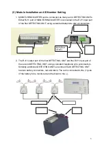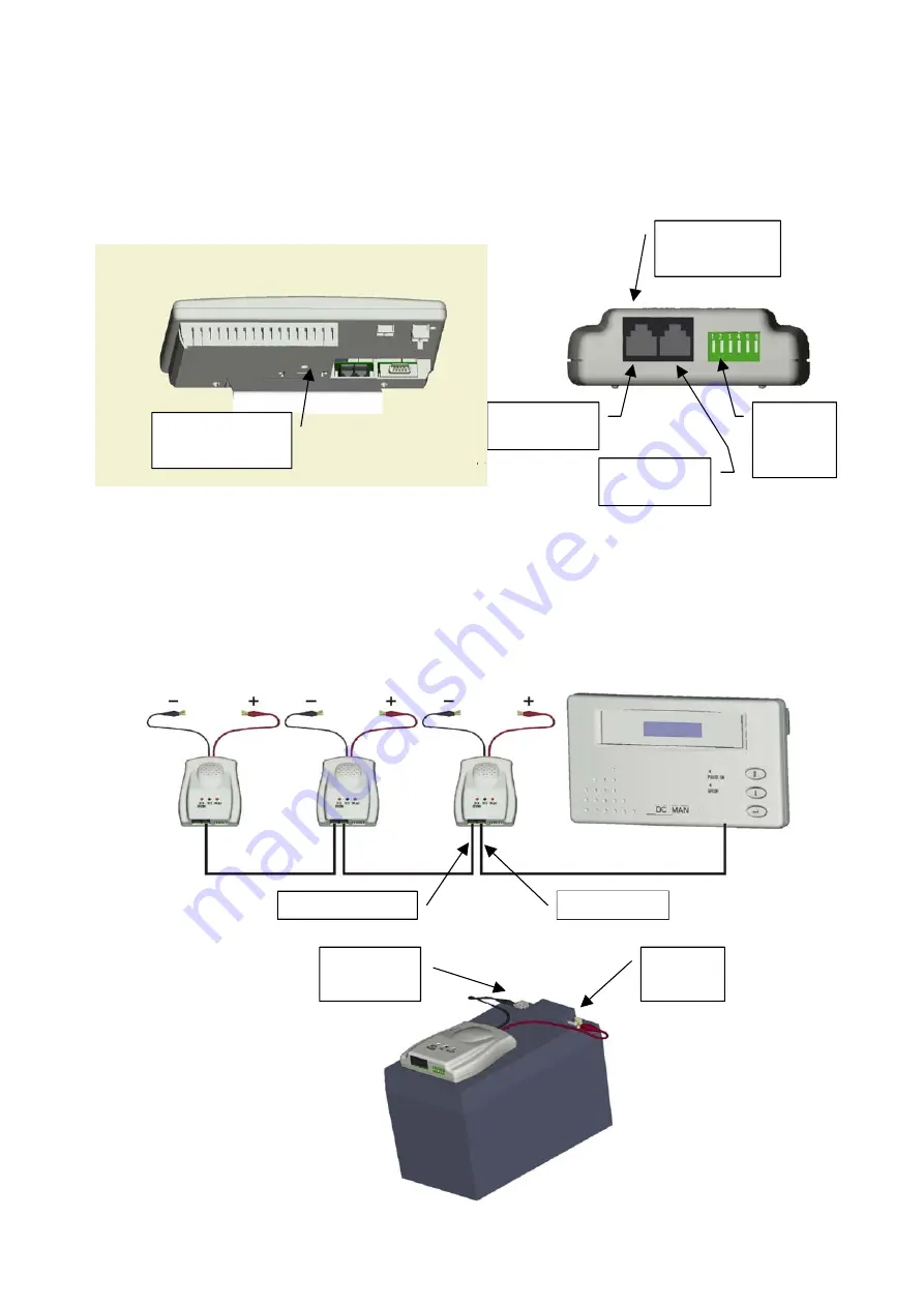
(C) Module Installation and ID Number Setting
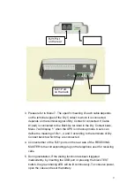
1. MONITORING MASTER can be connected as many as 64 DETECTING UNITs.
Either RJ11 port of MONITORING MASTER is connected to the RJ11 input port
of the first DETECTING UNIT, using a standard telephone wire w/connectors.
2. The RJ11 output port of the first DETECTING UNIT and the RJ11 input port of
the second DETECTING UNIT, using a standard telephone wire w/connectors.
Similarly, additional DETECTING UNITs are linked. Each DETECTING UNIT
has two battery connectors, red and black. The red is connected to the (+) pole
of the battery to be monitored and the black to the (-).
6 key
Dip
Switch
RJ11Port
(OUT)
RJ11 Port
(IN)
—
Pole
(black)
+
Pole
(red)
RJ11 Port on
the back
RJ11 (IN)
RJ11 (OUT)
RJ11 Port
on the rear
5
Содержание Triathlon III T3UPS-13-15K
Страница 18: ...1 7 Dimension Drawings 10KVA 60KVA OUTLINE DRAWING 1 13...
Страница 19: ...10KVA 60KVA INTERIOR DRAWING 1 14...
Страница 20: ...75KVA 160KVA OUTLINE DRAWING 1 15...
Страница 21: ...75KVA 160KVA INTERIOR DRAWING 1 16...
Страница 22: ...175KVA 320KVA OUTLINE DRAWING 1 17...
Страница 23: ...175KVA 320KVA INTERIOR DRAWING 1 18...
Страница 24: ...INTER PCB DIAGRAM 1 19...
Страница 31: ...1...
Страница 35: ...3 3...
Страница 70: ...ONE TO TWO SERIAL REDUNDANCY 8 3...
Страница 77: ...Appendices Additional Data on Options UPSCOMTM UPSCALLTM DCMANTM...
Страница 80: ...3...
Страница 81: ......

