9.
HELP
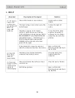
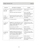
Abnormal
Description & Checkpoint
Solution
(1) AC input is
correct, but
rectifier does
not operate and
RECT AC
FAIL LED
The rectifier breaker is not switch on.
Switch on the rectifier
breaker.
The input voltage is not correct (out of the
normal range).
Connect the right AC
source.
lights up.
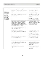
The phase sequence of AC input is
incorrect, input rotation error, and the
LCD will display warning message “RECT
PHASE ERROR” in the STATUS/WARN
menu (MAIN menu
→
SELECT menu
→
Correct the R.S.T. phase
sequence. Generally, to
exchange any two phases
connection can solve this
problem.
STATUS/WARN menu). ROTATION
ERROR LED on left side of the front
panel will also light.
If the abnormality cannot be corrected
Refer to PCB LED
when the solution actions have been taken.
Detecting Guide and check
the 3C PCB.
(2) The UPS
shuts down
under AC
mains failure.
The battery fuse (breaker/holder/dis-
connector) has not been closed.
Close the battery fuse
breaker/holder/dis-
connector.
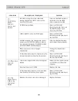
(3) No power
supply for UPS
control circuit
The reserve breaker has not been closed
(switched on).
Close the reserve breaker.
and LCD
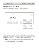
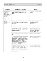
3B PCB has problem.
Refer to PCB LED
cannot display.
Detecting Guide and check
the 3B PCB.
9-1
Содержание T3UPS-13-20K
Страница 18: ...1 7 Dimension Drawings 10KVA 60KVA OUTLINE DRAWING 1 13...
Страница 19: ...10KVA 60KVA INTERIOR DRAWING 1 14...
Страница 20: ...75KVA 160KVA OUTLINE DRAWING 1 15...
Страница 21: ...75KVA 160KVA INTERIOR DRAWING 1 16...
Страница 22: ...175KVA 320KVA OUTLINE DRAWING 1 17...
Страница 23: ...175KVA 320KVA INTERIOR DRAWING 1 18...
Страница 24: ...INTER PCB DIAGRAM 1 19...
Страница 31: ...1...
Страница 35: ...3 3...
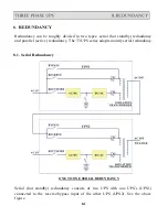
Страница 70: ...ONE TO TWO SERIAL REDUNDANCY 8 3...
Страница 77: ...Appendices Additional Data on Options UPSCOMTM UPSCALLTM DCMANTM...
Страница 80: ...3...
Страница 81: ......

