GeoCue TrueView 435 Скачать руководство пользователя страница 40

TrueView 435 Hardware User Guide 

40 

TrueView 435 Hardware User Guide    


10/26/2021 

Measuring GNSS Lever Arm Offsets  

To accurately position your LIDAR data, the position from the GNSS antenna must be transferred to the 
onboard positioning system. This is done by using lever arm offsets. If your system is mounted on an 
M600 with the GeoCue integration kit, the offsets have been preset by a GeoCue technician and should 
not need to be modified. If you are not using the GeoCue integration kit, or are installing the TrueView 
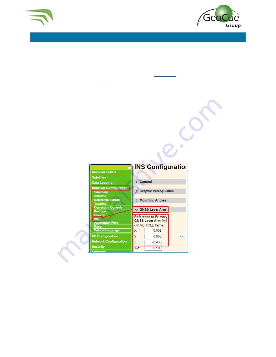
on a different aircraft, you will need to measure the offsets

then log in

 and enter them into the APX-15 

(Figure 53), or use 

CCFSection6 

 POS

 to update the values in the APX using the Core Configuration file 

(CCF).  

The position is referenced to the APX-15, which is enclosed inside of the housing and cannot be 
physically measured to. Therefore, you must measure to a physical point on the TrueView frame, then 
add or subtract offsets to the APX-15. The instructions below explain the physical reference points to 
measure to, and the offsets between those points and the APX-15. 

An assumption is made that the TrueView sensor will be aligned with the heading of the aircraft, and 
the aircraft will fly forward during data collection. The TrueView battery compartment is the front of 
the LIDAR sensor, so it should face the heading (front of aircraft). 


Figure 53 

 GNSS Lever Arm 


Содержание TrueView 435

Страница 1: ...TrueView 435 Hardware User Guide 10 26 2021 GeoCue Group Inc 10 26 2021 Version 1 0 2 Updated for Firmware Version 3 0 7 1...

Страница 2: ...300 TrueView Mounting Bracket 14 TrueView 3DIS Installation 17 TrueView Battery 21 TrueView Data Storage Devices 22 UMS 22 Camera SD Cards 22 System Configuration File SCF 22 Core Configuration File C...

Страница 3: ...rueView EVO 37 Logging in To APX15 37 Configure TrueView Wi fi 37 Log in to APX 15 39 Download T04 Files 39 Measuring GNSS Lever Arm Offsets 40 Z Offset 41 X Offset 42 Y Offset 43 TrueView 3DIS M600 P...

Страница 4: ...Terrasolid tools for kinematic LIDAR data production This was followed in 2009 by our acquisition of QCoherent Software LLC the creator of the point cloud exploitation toolset LP360 Today GeoCue is t...

Страница 5: ...ue 3D imaging sensor 3DIS With its wide 120 fused field of view the TrueView 435 provides high efficiency 3D color mapping and will redefine LIDAR wire extraction and dense vegetation penetration appl...

Страница 6: ...ate and Ronin mount were installed by a GeoCue technician If you purchased your M600 from a third party you will need to install these components before using your TrueView system The following steps...

Страница 7: ...h readout display c Set Screw 4 Figure 4 Figure 4 Set Screws d 50mm Spacer 4 Figure 5 Figure 5 Spacers e Hex Driver 1 5mm and 2mm Figure 6 Figure 6 Hex Driver 2 On the drone remove the four screws ind...

Страница 8: ...the four Set Screws and install in the empty screw spaces from Step 2 using a 1 5mm hex driver Figure 8 WARNING Do not overtighten If screws are too tight they will press into the plastic plate below...

Страница 9: ...removed in Step 2 Figure 10 and secure the plate to the top of the spacers Figure 11 Figure 10 Loctite the removed screws Figure 11 Install the controller box 6 Install the controller box on to the t...

Страница 10: ...ree screws on each leg of the stock mount Figure 12 Keep the screws they will be used again Figure 12 Remove stock mount screws 2 On the Ronin Mount loosen the screws that hold the legs to the rails e...

Страница 11: ...435 Hardware User Guide 10 26 2021 Figure 14 Rotate Legs 4 Using the screws removed from the drone in Step 1 apply Loctite to each screw and install the mount with the red lever facing the back of th...

Страница 12: ...rueView mounting bracket were installed by a GeoCue technician If you purchased your M300 from a third party you will need to install these components before using your TrueView system The following s...

Страница 13: ...ware User Guide 10 26 2021 d Threadlocker Removeable Blue 242 e 2 M3 x 0 5 8mm length screw f 2 M3 x 0 5 10mm length screw g 2 4mm Spacer Apply Threadlocker to all screws and tighten to 5 7 inch pound...

Страница 14: ...26 2021 Installing M300 TrueView Mounting Bracket i M300 TrueView mounting bracket Figure 20 with slanted TPU spacer Figure 22 attached Figure 20 M300 TrueView bracket j 2 M3 x 0 5 10mm length screw k...

Страница 15: ...h screws and install on the front two hole of the bracket and aircraft body The M3 nylon washers go between the M300 body and the TrueView bracket Figure 21 Tighten screws with torque wrench using 5 7...

Страница 16: ...eView 435 Hardware User Guide 10 26 2021 4 Apply thread locker to the M3 x 0 5 20mm screws and install the screw into the TrueView mounting bracket and aircraft body Figure 22 Tighten screws with torq...

Страница 17: ...surface with the landing gear down 2 Turn the red lever Figure 23 on the Ronin mount until it is loose but do not remove it completely Figure 23 Ronin mount locking lever 3 Align TrueView so that the...

Страница 18: ...ard through the upper metal plate of the TrueView and around one of the bars of the payload mount and close the safety lanyard Figure 26 Figure 26 Safety lanyard 7 Connect the USB or CAT6 cable to the...

Страница 19: ...ion on the connector Figure 28 Control box cable into TrueView 9 Attach the GNSS antenna cable to the TrueView unit Figure 28 and screw the antenna onto the antenna mount Figure 29 or insert into the...

Страница 20: ...TrueView 435 Hardware User Guide 20 TrueView 435 Hardware User Guide 10 26 2021 Figure 29 GNSS antenna...

Страница 21: ...does not use power from the power system of the aircraft and makes sure that TrueView does not interfere with critical flight functions You can expect to get about 90 minutes from each battery under...

Страница 22: ...2 format for firmware pre v2 0 3 3 114 GB minimum capacity 4 Need SystemConfiguration json and CoreConfiguration json files on the drive during operation Camera SD Cards 1 Format a 32GB card FAT32 b 6...

Страница 23: ...with a numeric value such as the Battery Status Percentage or Proximity Mode Distance Note It is recommended to open and modify the Core Configuration file with Notepad The following sections describ...

Страница 24: ...xtended mode and the images will not get transferred during wind down and they will have to be manually downloaded from each camera SD card and placed in the Camera 1 and Camera 2 folders in the cycle...

Страница 25: ...time frame We recommend 30 seconds as the default Laser Model must match the scanner being used A TrueView 410 should be 0 TrueView 600 series should be 1 TrueView 435 should be 2 The FrameRate shoul...

Страница 26: ...the TrueView controller box will be colored based on the percentage entered in the LowBatteryPercent and CriticalBatteryPercent fields The BAT light will be green if the battery is above the LowBatte...

Страница 27: ...YS light turns solid green indicating the system is recording data and ready for takeoff ProximityAutoStop determines if the system will automatically begin wind down when the sensors enter the Proxim...

Страница 28: ...use the user will need to determine how they plan to correct their flight data before collecting TrueView GNSS signals can be corrected by one of three methods 1 Single base Single base as the name im...

Страница 29: ...be used as a last resort option in the event of base station failure or lack of CORS network More information can be found in our knowledge base articles https support geocue com positioning options...

Страница 30: ...w will now cycle through the power up procedures 3 Disable Obstacle Avoidance IMPORTANT M300 Only The integration of the TrueView 3DIS system will cause disruption to the M300 s built in obstacle avoi...

Страница 31: ...to a TrueView 435 or DJI P1 or even switch to flying without a payload The aircraft must be in flight and hovering to start the calibration It is ideal to perform this calibration in a wind free envir...

Страница 32: ...This LED will flash yellow until GNSS signal is received then turn solid green c SYS The system light will flash yellow until the system is ready for operation When the system is ready it will begin...

Страница 33: ...takeoff a If proximity mode was disabled by the user wait for a solid yellow SYS light then press and hold the green button until the SYS light turns solid green 10 Turn the drone and transmitter on a...

Страница 34: ...eView 435 Hardware User Guide 10 26 2021 Figure 47 shows all the lighting sequences LED messages and their meanings Figure 48 shows how to interpret the symbols in the table Figure 47 Controller Box L...

Страница 35: ...t stick all the way back quickly and hold until the drone accelerates to 10m s This should take about four seconds Do not provide any other input The drone should be accelerating in a straight line ba...

Страница 36: ...flashing yellow 2 The flashing yellow light indicates the TrueView is writing data to the USB drive Be sure not to power off the TrueView or remove the USB drive during this period 3 When the system...

Страница 37: ...exploitation software LP360 and comes with all the same tools as LP360 Advanced Tools such as accuracy assessment automatic and manual ground classification and contour surface exporting See the True...

Страница 38: ...iew435 WiFi network 5 Scroll down to IP Settings and click edit 6 Change setting to Manual 7 Turn on IPv4 8 Set the following settings Figure 51 Figure 51 IP Settings 9 Click save You may need to rest...

Страница 39: ...red on your machine see Configure TrueView Wi fi 3 Open a web browser Google chrome Explorer Edge etc 4 Enter 192 168 2 160 into the address bar a When Applanix screen is visible enter username and pa...

Страница 40: ...in and enter them into the APX 15 Figure 53 or use CCFSection6 POS to update the values in the APX using the Core Configuration file CCF The position is referenced to the APX 15 which is enclosed insi...

Страница 41: ...where the cameras are attached The APX 15 is 1 644cm above this plate A tip for measuring Z is to install the TrueView and GNSS antenna on the aircraft and place it on a table Measure from the bottom...

Страница 42: ...heading of the aircraft If the antenna is forward of the APX 15 the X offset is positive If the antenna is behind the APX 15 the offset is negative The reference point is the rear aluminum mounting pl...

Страница 43: ...e aircraft If you are standing behind the aircraft looking in the direction of the heading the offset will be negative if the antenna is left of the centerline of the APX 15 The offset will be positiv...

Страница 44: ...ellow Red 2 GNSS Solid Green Valid date time stamp received 3 SYS Flashing Green TrueView has initialized ready for takeoff 20 Turn on drone controller then power on the drone as per normal operations...

Страница 45: ...be changed periodically A spare filter is included with your sensor spare parts The steps below explain how to change this filter 1 First locate the dust cover on your sensor For TrueView 400 and 500...

Страница 46: ...ve Figure 60 3 Remove the old filter from the dust cover 4 Replace the old filter with a new filter Figure 61 a It is advised to replace this filter with a new filter but it can be washed and used aga...

Страница 47: ...issues with PPK processing and accuracy The base station should be configured to record at 1Hz Question What are the base station requirements for the TrueView 3DIS Answer The minimum requirement bas...

Страница 48: ...encounter Click on the link and search for information contained in the knowledge base If a support request is sent during business hours a representative will typically get back to you within 4 hours...

Отзывы: